Janvantomme contributions


#1

Forum profile: @janvantomme
Contributor prefix: jv

objects
jv/math/constrain b input
jv/math/constrain b
jv/math/constrain p input
jv/math/constrain p

jv/lkm1636/lkm1638-buttons
jv/lkm1636/lkm1638-leds
jv/lkm1636/lkm1638-buttons-leds
jv/lkm1636/lkm1638-toggles-leds
jv/lkm1636/lkm1638-display-toggle-leds

jv/conv/pitch-randomizer

patches
Coming soon…


#2

jv/math/constrain

Status

active

Version

1.0.10

Description

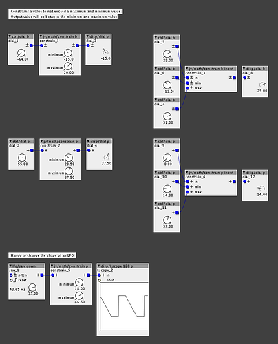
Constrains a value to not exceed a maximum and minimum value.

  • jv/math/constrain b input: bipolar version, with inlets.
  • jv/math/constrain b: bipolar version, with dials on the object.
  • jv/math/constrain p input: unipolar version, with inlets.
  • jv/math/constrain p: unipolar version, with dials on the object.

#3

Ahhhhhh. Very nice. Been waiting for something like this to come around.
Thanks:)


#4

jv/lkm1638

Some objects to work with the LKM1638 board.

Status

there may be small bugs…

Version

1.0.10

Description

  • jv/lkm1636/lkm1638-buttons: Reads the state of the buttons of the LKM1638 board.
  • jv/lkm1636/lkm1638-leds: Set the LEDs of the LKM1638 board individually.
  • jv/lkm1636/lkm1638-buttons-leds: Reads the state of the buttons of the LKM1638 board, and lights up the corresponding LED when the button is pressed.
  • jv/lkm1636/lkm1638-toggles-leds: Uses the buttons of the LKM1638 board as toggles. The LEDs shows which toggles are on.
  • jv/lkm1636/lkm1638-display-toggle-leds: Sets a text on the display of the LKM1638 board. Uses the buttons of the LKM1638 board as toggles. The LEDs shows which toggles are on.

Connecting the LKM1638 board
It's possible connecting Nextion lcd on axoloti pcb?
#5

jv/conv/pitch-randomizer

Status

active

Version

1.0.12

Description

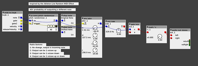
Object inspired by the Ableton Live Random MIDI Effect.

Use the number box to set a percentage. In the help patch, this is set to 40. This means that there is a 40% probability that the output will be a different note.

The radio buttons set the mode.

  1. Output is the same as the input, nothing changes.
  2. There's a 40% chance that the output will be one octave up.
  3. There's a 40% chance that the output will be one octave down.
  4. There's a 40% chance that the output will be one octave up or down.

Add an octave up and/or down
#6

jv/max11300/max11300-multi-output

Status

active

Version

1.0.12

Description

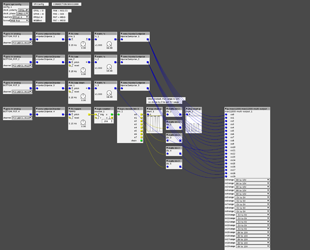
An object to communicate with the MAX11300 chip, providing 20 control voltage outputs to the Axoloti. Each of the outputs can be configured to output -5V to 5V or 0V to 10V.

Help Patch

  • Channels 0 to 4 output a sine wave LFO between 0V and 10V.
  • Channels 5 to 9 output a saw wave LFO between 0V and 5V, even though the output is set to -5V to 5V. This is because the output of the LFO is converted to a unipolar signal.
  • Channels 10 to 14 output a saw down wave LFO between -5V and 5V.
  • Channels 15 to 19 output a clock signal between 0V and 5V. Lowering the output voltage from 10V to 5V is done with the math/div 2 object. Each of these outputs sends out a clock at a different speed, the clock divider is created with the logic/counter and logic/decode/bin 8 objects.

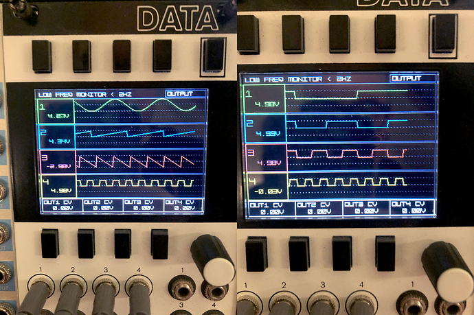
The photo below shows you the output captured with the Mordax DATA. On the left you'll see the LFOs and the clock signal, on the right the original clock signal + divided signals.


MAX11300 for CV-IN and CV-OUT
#7

hey this is cool, thanks a lot...do you mind to share a connection diagram for the max1300 and a suggestion for which of the max1300 is best to get? can this be modified to be oscillating in audiorange actually?

thanks a lot


#8

I've used the MAX11300PMB1 evaluation board for testing. The PIXI Click Board might work as well, but I haven't tested that one yet.

THE PMod connector of the MAX11300PMB1 can be connected to the Axoloti like this:

  • CS: Axoloti PA4
  • MISO: Axoloti PA7
  • MOSI: Axoloti PA7
  • SCLK: Axoloti PA5
  • GND: Axoloti GND
  • 3.3V: Axoloti VDD

There's also some jumpers on the board you'll need to connect to your eurorack power rails.

  • VDDIO: +12V
  • VSSIO: -12V

Picture of my test setup + lots more info can be found here:


#9

really really cool thanks a lot