Now that I've finished writing my book, it's time for me to build some actual instruments with Axoloti. I'll use this topic to document the process of connecting the LKM1638 board, so you have a starting point if you are interested in building an instrument with it.
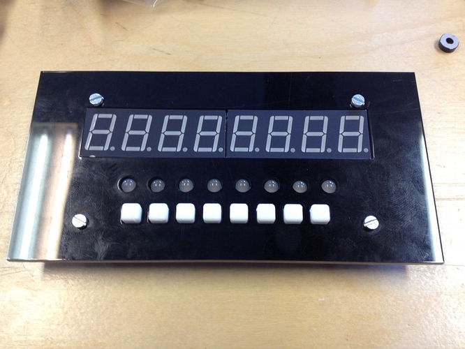
You can buy these boards for around €7 at DealExtreme. The specs of these boards:
- 8x 7-segment display
- 8x double-color green/red LED
- 8x button
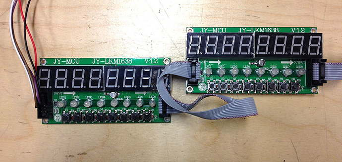
A great thing is that the boards can be chained, so you could use two of them to create a 16-step sequencer. The boards use the SPI bus on the Axoloti, so you will only need 4 GPIO ports.
Creating Objects
My goal is to develop some objects to work with this board. Some ideas:
- Send text to the 7-segment display
- Use the buttons as toggles, LEDs will show which toggle is on/off
- Use the buttons as a mini keyboard to play notes
- Use the buttons to toggle notes on/off in a sequencer.
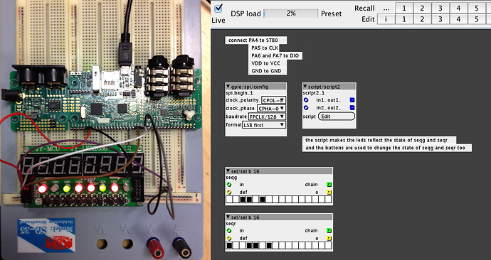
A good starting point to work with this board, and create objects is this old test patch made by @johannes.
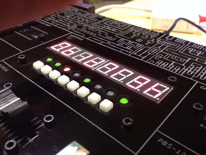
If you connect the board to the Axoloti Core and run the patch, you'll get something like the photo below. The sel/sel b 16 objects reflect the state of the LEDs. Buttons can be used to cycle through the LED colors.
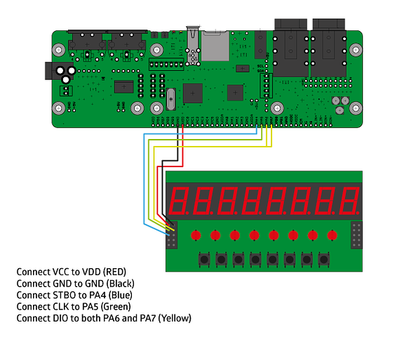
Circuit Diagram
- Connect VCC to VDD (RED)
- Connect GND to GND (Black)
- Connect STBO to PA4 (Blue)
- Connect CLK to PA5 (Green)
- Connect DIO to both PA6 and PA7 (Yellow)
Patches
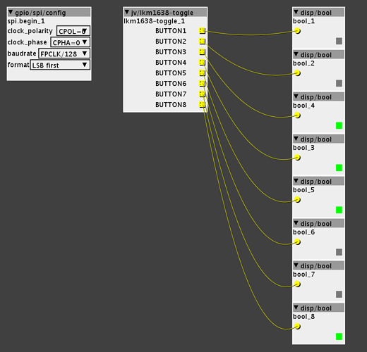
You'll need to add a gpio/spi/config object to every patch you want to use with this board. These are the settings for the object:
- clock_polarity: CPOL=0
- clock_phase: CPHA=0
- baudrate: FPCLK/128
- format: LSB first
Toggle Object
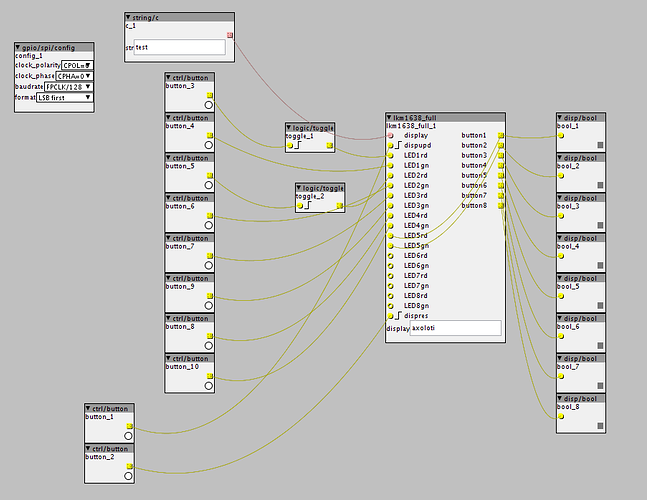
The first object I'm working on is a toggle object. The object will output booleans so you can use the 8 buttons on the board as toggles. The LEDs on the board will also reflect the state (on/off) of the toggle. A basic patch for the object looks like the screenshot below, I'll post the object once I'm finished writing code + testing.


 Super excited to try this out! You haven't mentioned whether two LKM1638 boards can be daisy chained together yet so I assume there isn't that capability yet. Do you know what's involved to make two units "talk" to one another? I could work on that part. I'm aiming to build a polysynth with built-in 64 step sequencer so 16 toggles would be ideal.
 if anybody is interested in using this object and is more fund of programming, this can certainly be solved.