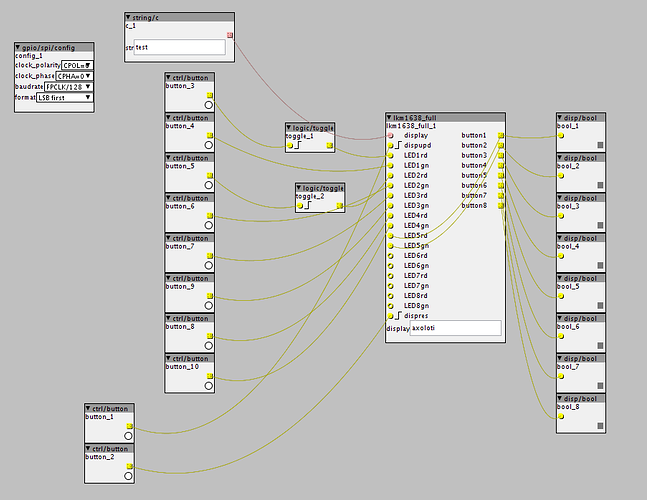
Hi Jan, just received the LKM1638 (x2) modules. I played with the .axh file you linked to above and managed to get IO working back and forth between the buttons and LEDS but as you mentioned daisy chaining doesn't work yet. I tried amending the code to extend daisy chaining capability but didn't have any luck, will dig through http://mjoldfield.github.io/pi-tm1638/tm1638_8h.html. I see great potential, especially if we can utilize the displays as well. Have you experimented more with these modules and Axoloti since?
Connecting the LKM1638 board
Haven't had the chance to do a lot of programming on the objects lately. Currently building a new dedicated synth with Axoloti that will use one of the LKM1638 boards as a control. When the synth is finished, I'll start programming again.
I'll stick with using one board for now, my second one got damaged while desoldering the connectors. If you want to solder the LKM board directly to the Axoloti, it's better to remove the black plastic part, end solder the wires directly to the pins and bend them over so you can mount it inside a case.
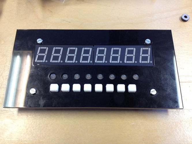
I did some tests with a lasercut top plate and 3D printed buttons as well.
That looks fantastic, bravo! I'm going to take a stab at developing the object to accommodate two LKM1638 boards because my intention is to have a functional 16 step sequencer. Getting both displays working would be overkill, for me at least. I will prioritise the functionality of the LEDs and buttons first. Where did you get your white buttons from? I see what you mean regarding the removal of the 10 pin connector, will try to not fry my second board 
I designed the white buttons myself, and printed them on my 3D printer. Just a plastic prototype for now, will print them in elastic material when I finish the synth.
Now that I've finished building my synth, I had some time to develop some objects to work with the LKM1638 board. I'll need to clean up the code and document everything a bit better, and then I'll publish them to the community library. This is what I've got so far:
- Read when buttons are pressed, no LED output.
- Read when buttons are pressed, LED output.
- LED output, no button interaction.
- Use buttons and LEDs as toggles.
The 7-segment display doesn't work yet, but I hope to make that work soon.
Here's some videos of the objects in action.
I've just posted some objects to work with the LKM1638 board to the community library. Feedback is welcome.
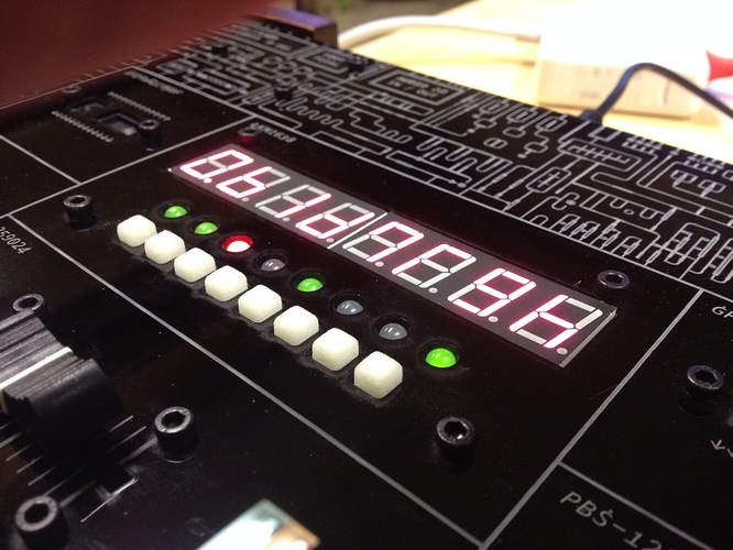
A bit hard to see in this smartphone picture, but I've got the display working tonight. Only thing I need to do now is creating a dedicated object to set the text.
Brilliant stuff, Jan! At this point I might be of some help. I'd like to think I'm good at testing and debugging after years of doing web development  Super excited to try this out! You haven't mentioned whether two LKM1638 boards can be daisy chained together yet so I assume there isn't that capability yet. Do you know what's involved to make two units "talk" to one another? I could work on that part. I'm aiming to build a polysynth with built-in 64 step sequencer so 16 toggles would be ideal.
There's no way to control two boards at the same time for now. And I don't plan on developing that since I don't need it for my synth. But I think you can adapt my code if you want to chain two boards.
This is a piece of code from my objects.
void tm1638_send_command(uint8_t x){
	SPID1.spi->CR1 |= SPI_CR1_BIDIOE;
	spiSelect(&SPID1);
	txbuf[0] = x;
	spiSend(&SPID1,1,&txbuf[0]);
	spiUnselect(&SPID1);
}
And this is the same function from this Raspberry PI library. ( https://github.com/mjoldfield/pi-tm1638/blob/master/src/tm1638.c ) You'll notice that the first parameter in this function, the variable t is a reference to a single board when they are chained together.
static void tm1638_send_command(const tm1638_p t, uint8_t x)
{
	bcm2835_gpio_write(t->strobe, LOW);
	delayMicroseconds(1);

	tm1638_send_raw(t, x);
	bcm2835_gpio_write(t->strobe, HIGH);

	delayMicroseconds(1);
}
My code uses the SPI API from the Axoloti firmware, the other code uses a BCM2835 GPIO library for the Raspberry PI that does something similar. You'll probably find a lot of Arduino code to work with the LKM1638 boards online that might help you figure things out.
Hi Jan, I am trying to get the LEDs and the display to work with the objects provided by you. I finally managed to hook this unit up to my axoloti and while the buttons are working, I get no response from neither the LEDS nor the 7-segment displays. I checked the unit with an arduino and it is just working fine.
I am using the example patches together with the exact same unit as shown in the photos, sourced from deal extreme a while ago. Any ideas? Any input appreciated, thanks, Christian
Can you try with this patch Johannes made? I sometimes had to run that one first in order for things to work.
Hi, I put some work into the original objects provided by @janvantomme. It is now possible to update the text display while the object is live. I am using this with a string mux object to display the name of the currently selected patch. I have also added inputs for both LED colors and an inlet to clear the text display.
What I did not manage to solve is that the patch will crash if you update the display too frequently/quickly. I was able to make it more tolerant by adding sleep-commands in a couple of places, this is for sure not the right way to do it. However, this is not a problem for me since I am triggering the patches with a midi floorboard, my feet are slow enough not to exceed the max frequency  if anybody is interested in using this object and is more fund of programming, this can certainly be solved.
Here are the links to the object and an example patch:
lkm 1638 object
lkm 1638 example patch
Thanks to @janvantomme for his work with this display module!
I only know the basics of C programming as well. The hardest thing now will be figuring out what functions to use to talk to the board via the SPI port.
Is it possible yet to chain two LKM1638 boards to get 16 steps and get the both displays to work also? I can't write my own objects. How many gpios would it use?
It's not possible with these objects. Two chained boards will only take up 4 gpio. Code will need some changes to be able to send data to, or read from two boards.
But it is possible to use two of these boards when theyre not chained? How many gpios would they use that way?
Don't think that will be possible. These board use the SPI protocol for communication. On the Axoloti, this protocol is implemented using the 4 gpio I've used here.
Okay, so not possible to use to of these chips. I might have to do an 8 step sequencer then. Or find some hacky way to use the 8 as 16. Or maybe its easy to just patch so i can have 16 step pattern i can browse with the 8 steps.
Thanks for your help. I had a year long pause from axoloti and now excited again to find some time to create something awesome.
Have you continued making the guide btw?
Hi @aslanov,
Thanks so much for your object and @janvantomme for the original ones.
I found a very simple solution for the update display problem:
I used a pulse/lfsburst4 object to trigger the update input and it works. No cpu spikes whatsoever!
I guess 'normal' triggers were too long...
Has anyone experienced that LED 8 is lighting up when sending update display messages?
My LKM board is slightly different (also very cheap and only red LEDs). I guess it's the board's design? Or could I perhaps change something in the code to change this behaviour? I'm just starting out with code so any help/insight would be really great! Thanks.


