MAX11300 for CV-IN and CV-OUT


#45

First post in the forum, I just wanted to thank all of you for experimenting and sharing your work on connecting the MAX11300 board to the axoloti. Since I am looking for ways to extend my Eurorack with custom modules, I bought it, used @mnskll SPI code for connecting the board and @weasel79 tips and everything else was pretty straight forward. By drilling holes in the MAX11300 board, it can be easily mounted directly on the Axoloti. I connected +12V/-12V to the MAX11300 board, which is recommendable (without that, it still works, but peaks, if you disconnect cables from other CV modules, which overloads the axoloti and leads to reboot)

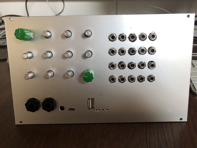
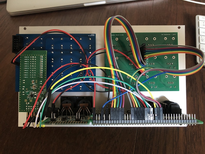
I share two pictures. By now I already extended the module with a second Input/Output Module, and I am going to build a third extension, just because it is easy and so powerful. Right now I am using it as Synth Voice with Gate/Pitch/FM CV In, the extension board (not on the photos) as a complex LFO generator with 6 CV outs, and by using a switch, all knobs are reassigned to control an overall Delay effect on the Synth voice and also on external audio input..

This combination is a great way to build a custom eurorack module, that can be everything you feel you are missing in the rack..

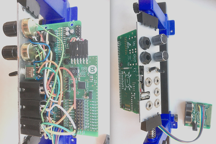
#46

awesome build, yeah the potential behind this is so endless..

currently building a second updated version too. one thing i do you also could think about, add a little OLED, maybe on an expansion frontplate.

also longterm it makes more sense to not mount the axo board directly to the frontplate, but instead as a second layer so you can add some i/o amping circuits and 3.5mm jacks. i guess good ole @paul did all this years ago...

i am starting to egt back into my synth build these last weeks, maybe lets collaborate on making some proper max11300 objects


#47

I agree: mounting the axoloti to the frontplate takes space - but I like it as a beginner, since accessing the usb port and SD card is easy that way. Also I have an oled & an encoder here for a second expansion board - but before I think I need to get rid of all the cables :wink:

I am thinking about designing a PCB + panel for this simple front panel configuration, that can be extended with expansion boards in a modular manner. Could be useful for beginners, e.g. as a nice workshop task and introduction in the axoloti for eurorack - or is there already work done in this direction?

What do you mean with max11300 objects - since it is only inputs and outputs in a patcher? Besides, well, I am not the best programmer - I just adapted the SPI code found in this topic here ..


#48

how does the dac/voltage range performance compare on this one? it's only 8 i/o, but cheaper and maybe that's enough for one board anyway. i2c/spi https://www.mouser.com/datasheet/2/609/AD5593R-1501709.pdf


#49

very interesting, i think 8 i/o are actually enough.
regarding the price though, if you compare bare chip prices or dev board prices, they are actually the same cost (9$ ish for the chip, 26 for the dev board respectively).
i am personally not fit to compare the power supply/analog filtering of the two boards, also it looks like you would need some external scaling to get bipolar voltages on the AD? and in order to get 0-10v you need an external VREF?
the max chip also has it going that good ole @mnskll already ported the drivers, but i'm sure it's quite easy to find some code for the AD chip somewhere and hack it into an axo object? it's just i2c after all.
anyways i am all for investigating alternatives!


#50

Had some PCBs made so I can finally develop some dedicated objects for the MAX11300. Currently using the MAX11300PMB1 evaluation board, but I've ordered some chips to see if I can build a dedicated eurorack module to be used with Axoloti or Teensy.


Janvantomme contributions
#51

Just stopping by to say this topic has been incredibly useful. I am an electronics noob, but by implementing all of your work here and editing the script a bit, I have 5 CV in and out working off my breadboard, with the MAX11300PMB1 powered from the Eurorack busboard.

Waiting on parts now to design a faceplate and rack everything up. Will post pics and more info once I'm finished.

Seriously stoked... The possibilities of Axo in the rack will be endless. Thanks everyone!


#52

I've created a dedicated object that works with the MAX11300PMB1 board. Outputs only for now, since I'm not planning on getting CV signals into my axoloti.


#53

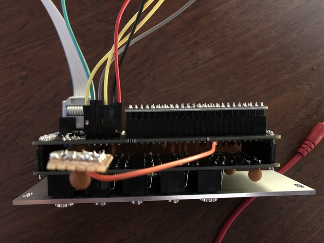
Made a dedicated eurorack module for the MAX11300 so it doesn't take up that much space in my rack. 20x CV outputs in only 8HP. Had to solder in a small extra circuit to make it work for now, so I'll have to add that to the next version. But it looks like everything works for now.


#54

This is modulation the likes of which very few ever seen!


#55

Were you able to calibrate to 1v/oct or is it for rough modulation only?


#56

I made a 1v/oct object, but still need to test it a bit more before I publish it.


#57

I would be really interested to get some eurorack modules based on the axoloti. Are you also planning to sell these? Any plans for also making a CV-input module?


#58

In theory, the module I have should also work for inputs, since the MAX11300 is configurable. I didn't manage to make the code for the inputs work for me yet.

I might sell these in the future, but won't make any promises yet. There is still a lot to do in order to make this a real product and start a small production run.


#59

If you get the MAX11300PMB1, do you need to buy that usb adapter as well?


#60

No. You don't need it.


#61

when you do get inputs sorted I'm very much interested


#62

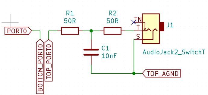
It seems that the MAX11300 has current limiting resistors baked in. How much extra circuitry did you add to the outputs for further protection and would I need more circuit protection for inputs?


#63

I've just added 2x 50 Ohm resistors and a 10 nF capacitor.

Inputs should probably work with the same circuit, as everything can be configured in software. So you can configure the port as input/output and also set the range (-5V to 5V or 0V to 10V).

Not sure what happens when you configure a port as a -5V to 5V input, and then plug in a 10V signal.


#64

Good info! Thanks you.