Eurorack Interface Boards here >>


#1

HI Everyone,

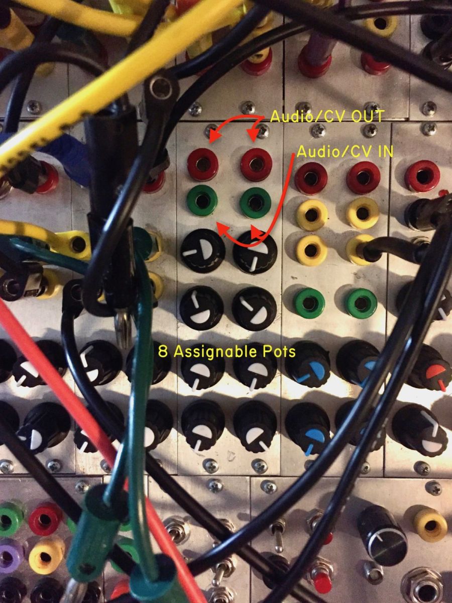
In my Eurorack system, I use 3 8hp Axoloti modules that I've DIYed. My modules have 8 assignable pots, audio out, and audio in/CV with clipping protection so higher voltage Eurorack modules won't fry the Axo. I'm offering some of the spare PCB boards from my project for sale if people are interested. I teach beginning soldering workshops occasionally, and I think this would be a pretty easy DIY project even for total beginners. If there's interest, I'd consider doing a revision (or a second run with PCB/Panel kits maybe) and incorporating some other ideas.

Here's what the Axoloti modules look like in my own system. My system uses banana jacks, but it's Eurorack in every other way, and you can use whatever jacks you want. Please pardon the spaghetti.
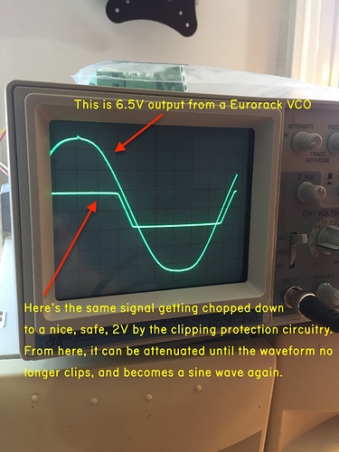
Here's what the protection circuit does. Axo can be damaged by voltage exceeding 3.3v.

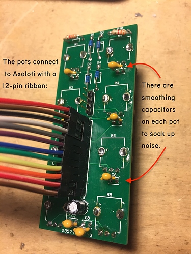
This is the back of the board -- the smoothing caps add a layer of defense against unwanted system noise, and help with analog to digital jitter a little bit. You could probably use larger caps and slew to your taste.

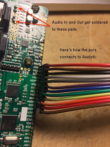
Here we are connected to the Axoloti:

Here's a vid of the pots talking to Axo. I can share the user device I made if you'd like.

$10. It can be yours! lolol. Comment here with questions or if you want one.


6hp eurorack conversion
[Need Help with SPI] Euxoloti for axoloti (Eurorack Module)
#2

Very interesting do you have schematics ? Did you have to cut the axoloti boards midi ports to fit into eurorack ?


#3

Yes, you have to cut the board along the perforations. In my personal projects, I also desolder the midi jacks and replace them with 3.5mm jacks, but this isn't necessary.

The schematic is dead simple -- just a diode clip. I've posted it and discussed it numerous times in this forum, so if you do a name search of my name, you should be able to find it without much difficulty. The pots just have a 10uF cap on the +v rail going to ground, and 0.1uF (but feel free to choose a larger value) between the output and ground.

My first Axoloti projects a few years ago used panel mounted pots wired directly to the Axoloti with flying +v and ground. Also, I had the clipping circuit in the kludge area of the Axoloti board. The pots were noisy and occasionally shorted. I made these PCBs just to fix all of those issues and make the wiring cleaner and more convenient. Just made it for myself, but I have some extras, and if there's interest enough, I'll do another run of them.


#4

recently discussed here: https://sebiik.github.io/community.axoloti.com.backup/t/can-i-make-cv-inputs-with-vactrols/5578

and here:


#5

Thanks for this, I'd like to buy three of your boards or what you can provide.

By the way, I cut my first board on the perfs. the other day and its a dream with a Dremel tool armed with one of the small cutting discs, it goes through like butter.


#6

Hey Jonas, nice to see you here as well as Video Circuits on facebook. I'd definitely be interested in a pcb/panel set, though would happily get just the pcb if revisions don't happen!

With regards to ideas for a second run. My own personal preference would be to incorporate more I/O, possibly through the max1130 chip: https://sebiik.github.io/community.axoloti.com.backup/t/max11300-for-cv-in-and-cv-out/
I would also personally expose the midi jacks, sd card, usb but I'm sure I could DIY that if needed.

Other than that the possibility to include an oled ala this thread for patch switching etc. would be amazing.
https://sebiik.github.io/community.axoloti.com.backup/t/spi-i2c-oled-display/

Obviously both of those are big changes & would take a lot of work (and I imagine might not fit your use case) but hey, those are some ideas for expansion that might be useful.


#7

thanks you two -- you can email me at jonasbers@jonasbers.com. send your address and how many you want. I'll get them out to you right away.

@blackmountain -- yeah, i agree, it's not too bad cutting them. I've done three of mine now. The first one was a bit scary, but now it's not a big deal. i just used a hacksaw.

@awolch-- HI! nice to see a fellow video-head. I agree with the things you suggested, though it might be a while (or maybe never) until i attack something like that. If you look in the other threads you can see how i did my usb jacks. I hate the tiny usb jack and replaced it with a normal sized one. also, IMHO, a din jack is the incorrect footprint for midi in a modular synth, so i replaced mine with 3.5mm jacks.


#8

Hey Jonas,

I'm also interested in a PCB.

Thanks for this, this may be exactly what I need :slight_smile:


#9

Just checking back in. DM me on here or email me at jonasbers@jonasbers.com to arrange shipping if you'd like to purchase a board.


#10

OK, I have an improved version of this now. I'm going to reduce the price of the original one to $5 US + shipping, and offer the new revision at $10 + shipping. The newer version has a better ground plane and holes to solder the input wires to (on the original one, you have to solder the input jack wires to resistor legs). In practice, I doubt any of this would make a significant difference, but I made the improvements for myself, and I wanted to offer it to you as well.

A few of you have posted here saying that you want one, but haven't emailed me yet. Again, just send an email to me at jonasbers@jonasbers.com -- let me know which version you want (new or old) and we'll arrange shipping.


#11

Thanks to those of you that put orders in! Here are the new boards and also some pics of a complete module.

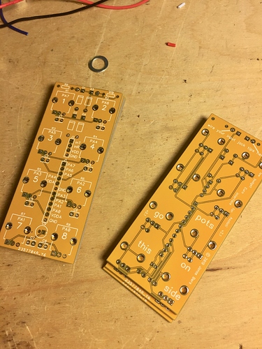
The new boards have an improved ground plane and are labeled to make things a little easier:

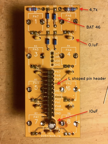
This is a fully populated board. There's some leeway with the component values, but here's what I used. The resistors in the picture aren't actually 4.7k, but they should/will be. [note the L-shaped pin header row -- I use it to mount the Axoloti to the PCB]:

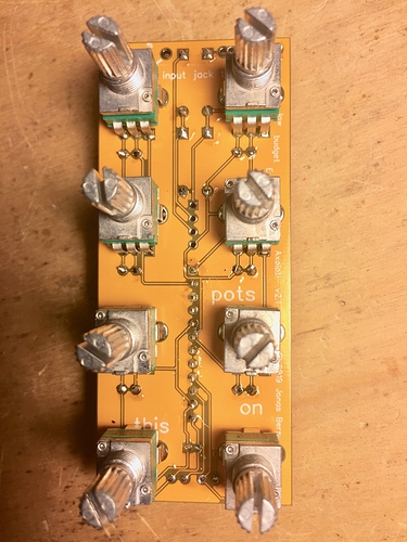
Here's the pot side. I used 20k, but I think @johannes recommended 100k.

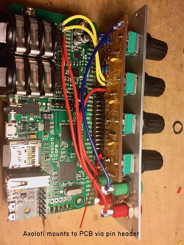
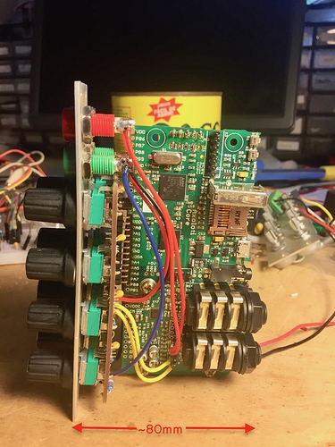
Here's how the Axoloti is mounted to the PCB via the L-shaped pin header. You could use some sort of mounting hardware I guess, but this seems solid enough. The output jacks are wired directly to the TRS output (red wires). The input jacks are wired to the board (blue wires), where the signal passes through a clipping circuit and then gets wired to the TRS input (yellow wires). The board is labeled to make this easier. VDD for the clipping circuit is also wired to the PCB with an isolated ground.

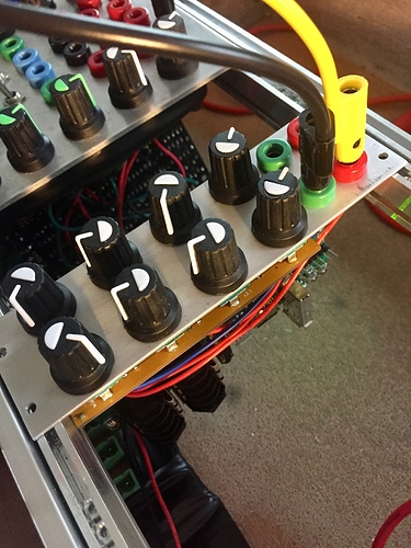
The PCB mounts to a panel via the pots. Also, I use banana jacks, but there's no reason you couldn't use panel-mount 3.5mm jacks for a typical Eurorack system. The mounting depth isn't exactly "skiff friendly", but the panel is nice and narrow at a svelte 8hp, which was more important to me.

Here's a completed module in the case, powered up and not on fire:


#12

I still have a few of these left if anyone is interested.


#13

there's one left from the first run. I'm sending a bunch of things out to fab next week, so I can include more of these in my next order if anyone wants a few. it might be several months until I do more unless i hear from anyone.

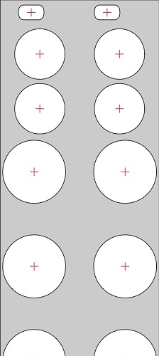
Also, here's the panel drill guide for v2:

The panels in my system are slightly narrower than 8hp, so just center this manually and you'll be good to go.


#14

Hey @JonasBers, thanks for sharing this build! I made something based off of this tread and it seems to work well; now I'm busy programming the axo.

One question:
You don't protect the outputs in any way. Do you know if there is any danger if one were to say accidentally patch a ~5v signal into one of the unprotected outs?

I was trying to find a diode schematic that would prevent the signal from entering one of the outs but didn't figure out what would work given my limited knowledge of electronics.


#15

no prob @philomates. I've accidentally patched a +/-10v oscillator to the Axo output and it didn't die, which isn't to say that it couldn't. my board was designed with efficiency in mind, but if I was going to do it correctly I'd use op-amp based input and output buffers. Another diode clip might work, but a series diode would form a half-wave rectifier and clip the negative peaks of the output audio waveforms.


#16

Hey, you still make these boards? Have you developed them further?


#17

Yes and no. The nice yellow ones are sold out, but I still have a box of the first run green boards. The first run is functionally identical, but isn't labeled and the pot lugs aren't grounded. Just for best practice, I made a bigger ground plane and grounded the pot bodies in the revision, but I didn't notice any difference in performance. It's unlikely I'll do another run of the labeled yellow PCBs, but the old green ones are on sale for $5. US shipping is $1. International shipping might be up to $5 depending on the country.

Contact me though my site link below if you (or anyone) wants to order. https://jonasbers.com/booking/