Is there any reason I can't control axoloti parameters with cv signals lighting up leds connected to ldrs which are connected to axolotis analog ins?
Can I make cv inputs with vactrols?
no, not as far as i can tell. just make sure you don't blow the led's up when connecting cv...
I tried lighting leds with cv. I had 220ohm resistors and everything was fine.
This is awesome information. So I can very easily add cv inputs to axoloti now! Why haven't I seen this here before.
Now I can use my microbrutes cv's to control axolotis sound easily. This is so awesome.
hmm, i guess the ldrs are not really linear, so it will mess with your cv information volt per octave will not be volt per octave anymore. so i guess for pitch information this will not work properly. also not sure about the temperature stability of ldrs so, maybe it will drift with temperature change. but there are many guitar pedals that use the vactrol approach to get a variable resistance from a voltage source (compressors etc.) so definitely look into it!
Yea, i don't need it for pitch. I'll use it for creative modulation of the sounds. I just want the sounds be alive about the same style as my microbrutes sounds. So it could work for that, right?
yes, i think so. another reason why nobody did this for axoloti might be that vactrols are quite expensive.
Do you know if I need to wire anything between the ldr and the analog in, resistor or something?
yes, you want to create a voltage divider and read the resistance change that way. you will have to experiment with resistor values, try 10k as a starting point.
so one end of the 10k resistor to 3.3v the other end to one of the ldrs legs. the other leg of the ldr to ground. junction of resistor and ldr goes to analog in.
So using a potentiometer as a resistor is a good idea? That way i could change the resistance in realtime.
just make sure you don't turn down the resistance to zero on the pot and at the same time you send full brightness to the ldr, otherwise you create a short from 3.3v to ground. i would not go lower then 1k
The trouble with Vactrols is that they are not very accurate and you have to match them if you are going to use more than one. Also they are not particularly fast either. It is much simpler to use a simple transistor circuit where the transistor is controlled bt the external CV to open or close the voltage from a fixed source that can never get more than the Axo wants to see. Transistors are much cheaper than Vactrols too.
For some reason I thought the vactrol way would be simplest way of doing this. How would a simple transistor circuit be used for this?
my experience with transistors was, that they are also not very accurate, especially when used not as a switch (open/close) but as a voltage "following" amplifier. did you get consistent results with a transistor setup that way?
this can be a blessing and a curse i guess... and it is not necessarily true either. there are very fast vactrols around, that can detect very fast frequency changes. (so fast indeed, that you can introduce 12khz whine with a PWMd LED for example) i assumed also that all they were not very fast and once got a very lengthy email from a guitar pedal guru, explaining that all in detail...
I/O circuits for CV are listed on the 'official' hardware pin out doc
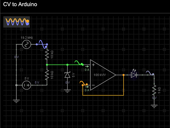
And my own (as it happened) unnecessary post includes a link to a lovely circuit simulation of the CV->Axoloti circuit route. Requires signup but its awesome, you even get to see the electrons flowing around it.
But I’ve run this simulation and added a voltmeter at the outpu and the output is 5v so it’s not quite as advertised. Some adjustment is needed.


