I can't read schematics  that's why Im thinking the vactrol solution would be easier for me. But thanks for your answer. That looks complicated to me but it probably isn't. So you have tried that abd it works?
Can I make cv inputs with vactrols?
No I haven't but once I have time to stop researching and start playing I probably will 
I guess this was relevant, and you interacted on this thread. I surmised from it that optocouplers were only handling gates from this.
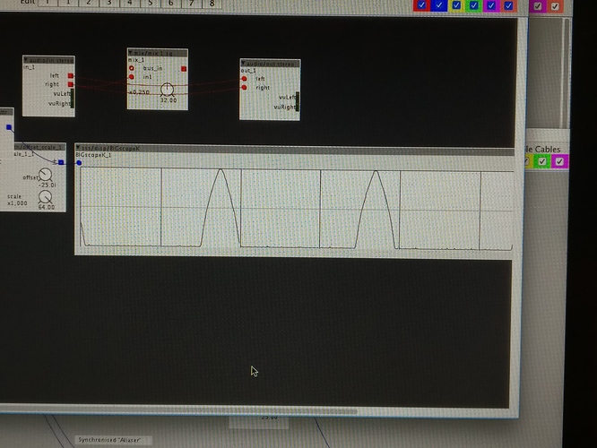
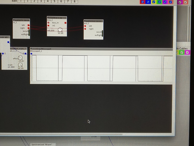
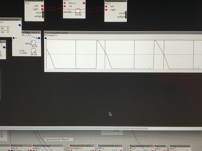
Now im testing the diy vactrol cv input. First feelings are impressed. I see from the scope that its accurate enough to draw the waveform to the scope.
Its only 220ohm . I tried with 10k but didnt ger any signal.
Edit:
Now i tried again with 10k and it works. I guess i had some wrong wiring first. I wonder if i did some damage with too small resistor
There is a nice kit (you can also order only the tiny pcb) by Synthrotek called VacPac that allows you to adjust the behaviour of the Vactrol. I use them a lot for CV to resistance tasks.
Cool, i wonder if i could adjust the scale with diy methods. I guess it's a different tjing to adjust the scale via axoloti patch objects versus adjust it by components 
Is there any way to make lde respond from lower light? Is that sensitivity depending on the resistor?
yes, the responsiveness depends on the ldr you are using. so i would rather build a circuit that can boost or attenuate the incoming signal before it hits the LED in order to get the desired response.
in your case (with the circuit i described in the initial posts) if you change the resistor to VDD you can alter the range(or more precisely the behavior) quite a bit, so try to use a 1k resistor and add a pot of 10k in series.
The zener breakdown is 5v, but you want 3.3v. You might be better off using a schottky up to VDD instead. Also, is the LED meant to be acting as a half-wave rectifier? Another schottky to ground at the same node as the positive going one would potentially serve that purpose better (and without voltage drop). A transistor to light the LED is the standard solution.
I've used this circuit for over a year in a +/-5v modular system without issue. I just manually bias CV with a patched offset voltage sum and then attenuate. 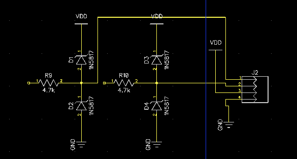
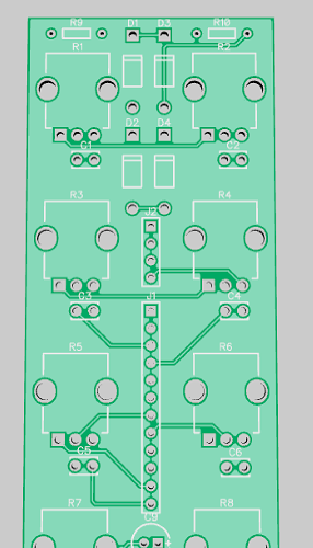
I actually just sent this proto out for fab last week -- it's the clamp circuit for 2 CV inputs, and 8 pots with smoothing caps for Axo. If it works properly, I'll throw the gerbers up on my site for download.

