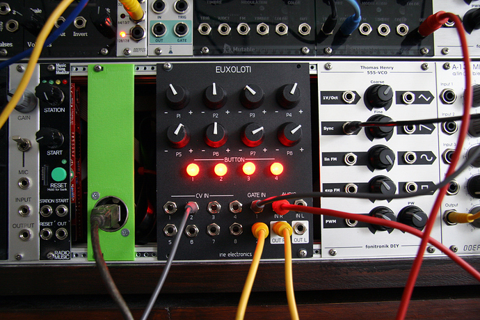
[Need Help with SPI] Euxoloti for axoloti (Eurorack Module)

modular

#36

What jacks will you use for the control board?
If you are planing to use the PJ301BM (very standard on modular) I really encourage you to use dual (Banana-Jack) Eagle Library.

You can copy paste it from any of the eagle files from Befaco modules

This library let you choose to solder PJ301BM Minijacks or Truconnect Bananas used often by DIYers


#37

@kassu: I used the external ADC because they will reduce the necessary pins by the axoloti core and protection parts. Just 6 pinouts instead of 16 and the MCP3208 ADC has built-in diode protection to safely clip the voltage for axoloti.

VDD and Vref of the ADC come from axoloti's VDD (3,3V). The 7805 is just used to power the axoloti core and its voltage regulation will convert it to 3,3V VDD. Check axoloti schematic page 2
The LM4040 10V Vref gets its supply from the -12V of the Eurorack power supply.

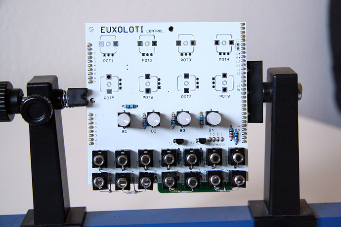
@Diego: Thanks for the hint. It will be good option for the secound control PCB run with larger dimension. The actual PCB size is 10*10cm to reduce the prototyping costs. The jacks of the control PCB are at the moment the standard "Thonkiconn" 3,5mm jacks.

so I'm out for this year :wink:. everyone a happy new year


#38

paul ... this is awesome but cv out would be even awesomer! then you could build hybrid synths with digital oscillators from the axos audio + real analog filters + vcas from euro. 4 cv outs would give you a duophonic hybrid synth. digital audio + analog processing is the new frontier!


#39

that's really good idea and I agree with you. I will try to work on an extension module. When I started with euxoloti, I was thinking about a core module which will be extendable like the turing machine from music thing. The biggest problems will be first the necessary cpu resources for processing the whole I/Os and the second will be to reduce the latency.

A SPI DAC will only need 3 pinouts. Two of them are main SPI pinouts (MOSI, SCK) and the third will be further digital pin for CS/NSS. So no problem to hook up many DACs to euxoloti core.
The tides module from mutable instrument uses a DAC8552 16bit low glitch DAC and voltage shifter, but the dac8552 is a msop package. I don't know how much of you are skilled with hand soldering smd parts but it's not to difficult.
If I can organize an order at mouser or digikey, I will order one of the dac8552 and test it with the axoloti. The IC is not available in europe or very expensive (doubled price)…
An other solution can be a DAC + Mutliplexer + sample & hold circuit as rvense mentioned at the DAC thread.

But first I want to finish the core project and then develop further extension boards (CV out, Gate out etc.). By the way: The panel, core and control pcbs are shipped and will be arrive in the next two weeks.


#40

3 posts were merged into an existing topic: Raw axoloti brick


#41

sound good, paul. i have a lot of experience controlling my modular via püre data / es3 8-channel dac and its really important to have a low jitter dac with very high precision. otherwise things like frequency modulations dont sound good. that and you need a full -10v/+10v output.


#43

The tides module from mutable instrument2 uses a DAC85522 16bit low glitch DAC and voltage shifter, but the dac8552 is a msop package. I don't know how much of you are skilled with hand soldering smd parts but it's not to difficult.

FWIW, if "very high precision" is really important, better to look at Yarns (same TI family, but quad). The output buffer from Tides or Peaks isn't geared towards DC precision, Yarns's is.


#44

thanks for the hint, I will check the schematics later. I think a 1V/Oct output will be realizable, but I can not ensure a precision range of 10Vpp at the moment. I have to do some math and try it.

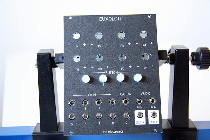
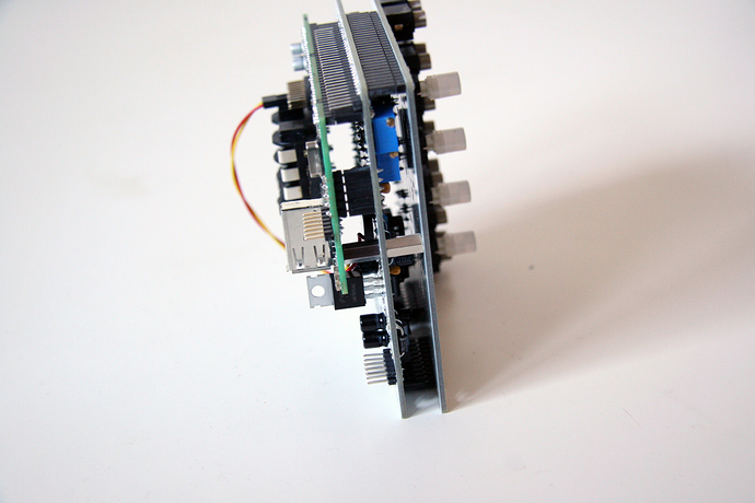
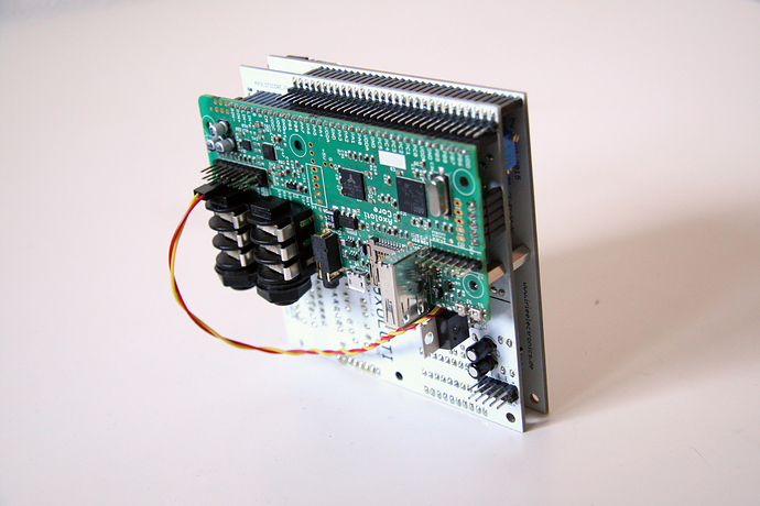
Here are some reports and photos of the actual build state:

  • CV IN works, but if an other source with a new GND is connected, the axoloti will be disconnected form the computer. The axoloti itself works forward, no drop outs or else. Jitter is less then +/- 0,1 of 64. Maybe someone knows the reason of the GND problem. Schematics are at github
  • GATE IN works, same GND problem as CV IN
  • AUDIO OUT works fine.
  • AUDIO IN, I did a big mistake and route the a-in signal to the wrong inputs :smirk:
  • PUSH BUTTON and LED work fine

  • Pots haven't arrived till yet.


#45

15 posts were split to a new topic: MAX11300 for CV-OUT and CV-OUT


#51

The inv buffer is biased by the CM voltage. It was discussed previously. LIN+ and RIN+ are connected together and biased. Each audio input should be connected to LIN- or RIN-. The corrected schematic /REV2 will be online later.

For now everything (pots are unchecked) works fine. But there is the GND problem.


#52

trying to understand what is happening here...

You're plugging in a new source into a cv-in jack? From within the same eurorack system? If the cv-out source is not at zero and is of low impedance, inserting will connect that voltage source to ground first.
Or is the cv-source coming from something pc-connected?
If the cv source is an isolated device (separate ac adapter or its own battery power), I can't see why that 'd happen.


#53

The euxoloti and axoloti is powered by an external +/-12V power source. The axoloti is powered by the +5V regulator from the euxoloti and vbus send is active. The axoloti core is also connected to the axoloti patcher.

When I connect any external source (CV, Gate, Audio in) from an other power source to the jacks of the euxoloti, the axoloti will be disconnected from the mac. But if a new source from an already connected GND is added, the axoloti stay connected. So it's seems like a GND issue.


#54

The inv buffer is biased by the CM voltage

Well, I've looked at the schematic, so I've seen that. CM = 1.65V, no? So I calculate V_out = 1.65V*(3.3/22+1) = 1.8975V. So a typical signal will swing around 1.9V, from 1.15V to 2.65V; which is what I was wondering about. Nevermind


#55

IM HOOOOKED :smiley: hahahaha looks so sweet cant wait is it possible to preorder?!


#56

Hey :smile:

I was wondering.. would it be hard to add cv out.. just thinkin loud :smiley:

really looking forward


#60

UPDATE Euxoloti and beta tester

hi folks,
the pots arrived yesterday after 3 weeks of waiting. :pensive: So it seems that the Euxoloti is running fine till now.:grinning: I have to make some modification.

check the short audio demo

Now I want to start a community beta test session.
Does anyone want to join the develop & debug process?
I have some PCBs left and I'm looking for people who are skilled in axoloti, soldering, electronics &/or programming. To own a modular synth system would be helpful too.

If you want to join the process, I will offer you both PCBs (Euxoloti Core & Control) for 8€ (prime cost) + shipping. Further PCBs will be offer for prime cost, too.

Cause of spam protection, you have to use the contact form to join the process.
Contact Form


#61

I'm tempted to join the beta, but wonder what modifications you still have in mind. If they're major additions, I will hold off for a while.

a|x


#62

hi alx,
this are the actual modifications:
- the audio input routing has to be reroute to its neighbor pin.
- some component values has been changed (updated BOM and mouser card)
- maybe LEDs will be connected to axoloti PWM out pin…
- Final Control pcb will be larger for the lowest jacks. (check above pictures)

I will send each one detailed descriptions.
Part cost for core pcb ca. 30€ (Axoloti and pcb not included)
Part cost for control pcb ca. 50€


#63

Cool.
So the necessary changes could be made with some jumper wires, and the existing PCBs?

a|x


#64

Same here. I'm kind of torn between doing this myself and being lazy, i.e. getting yours.

My main quibble:
What rate are the CVs sampled at? I understand the F4 ADCs don't have the best reputation, but will using a MCP3208 really improve things in any way? Note how they've entirely disappeared from the Mutable Instruments stuff.