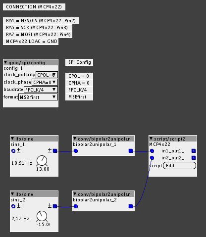
[GPIO I/O] Example DAC MCP4x22 & SPI


#1

Hi,

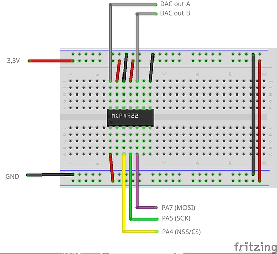
motivated by a request of cereyanlimusiki at my "Euxoloti for axoloti (Eurorack Module)" Thread, I tried some MCP4922 and MCP4822 DACs to generate some CV outs. Vrefs and VCC should be decoupled by 100n capacitors.

Don't forget, the axoloti core has two dac outs (PA4/PA5).

Download Patch: spi mcp4x22.axp (4.0 KB)

Schematic:


How to get a maximum of knobs on a axoloti core?
Questions about PWM output and A/D input 12 bit
#2

A common technique to get many analogue outputs from one DAC is a sample and hold. It's basically a switch (4051 or similar), capacitors, and op amps. However, it requires rather precisely synchronised control over the timing of the DAC output and the control of the switches. Would this be possible to wire up in the patcher, or would a new module need to be written?

I've done it on an STM32F4 before, using the built-in DAC and a few GPIO to control the switch, so I know it can work (and I'd guess give as many CV outputs as anyone would ever need if the DAC is fast enough), but I'm unsure how to get it to work with SPI since the synchronization is rather important. I'm guessing the DAC doesn't start changing its voltage until 16 or however many clocks after you write the data to the SPI buffer, and I don't know how you'd switch GPIO synchronised to that?

With the built-in DAC it should be fairly simple. I can dig out the old code to see exactly what I did. With two DAC outs you should be able to get 10 CV outs at control rates I'd think. I think I got six in all at audio rate, but never tested how many I could get since the maths I was doing to generate the signals were quite heavy and the F407 wasn't up to it, at least not the way I'd structured my code.


#3

I just tested this out. There's a lot of aliasing when running the oscillator at 200Hz. Removing the sleep in the last line of the script makes it better. I think the script object itself adds the needed delays.


#4

ok, good hint. I paste the delay, because my board often stops working by an data overflow.

your explanation about the s&h dac seems very interesting. can you work out and show us your method more detailed? I'm new to the stm32 family and don't know much about this.


#5

Well, it seems stable here without the delay. Maybe things were cleaned up further down since you tried.

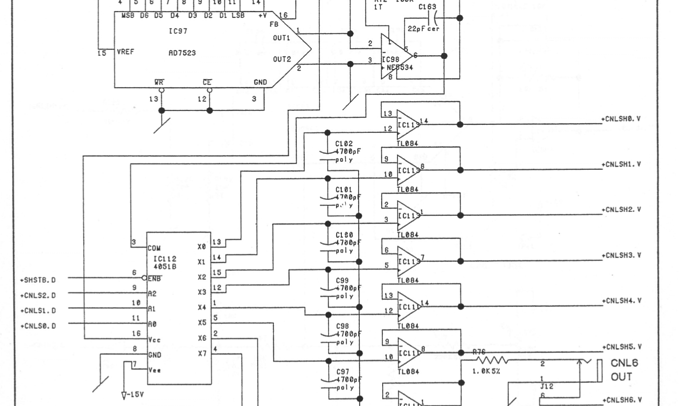
Sample and hold is basically what the name implies, the voltage coming out is sampled and held at a specific value for a while. This means you can free up the DAC. This is the SP1200 schematic to see how simple it is to implement:

The AD7523 is not actually the main DAC, it's used as a digital gain control -- the actual audio signal comes as a voltage from another DAC further up and is used as the voltage reference. IC98 converts the output current to a voltage. That's not important, so we'll just refer to what comes out of IC98 as 'the output signal' and everything before it up until the data input from the sound memory as 'the DAC'.

First, the output DAC here, unlike the codec you'd use in a modern system, does not have a clock per se. It just changes its output value when you change its input, like the MCP4x22. So what we can do is send several signals interleaved, first a single sample from signal 1, then a single sample from signal 2, etc. The analogue signal the results from this is obviously messy, a bunch of signals overlaid.

This output signal goes into the 4051. If you don't know this chip, it has one common terminal that can be connected to one of eight other terminals, based on a 3 bit digital input. The 4051 works both ways, one of many inputs to a single output, or a single input to one of 8 destinations.

Remember we have exact control and knowledge of when the DAC converts a sample, so we can generate a signal to control the 4051 that's exactly in time with when the input to the DAC changes, ie., when the output signal is a sample from signal 1, the 4051 switches the voltage to output 1, and then just as the DAC changes its output to a sample from signal 2, the 4051 switches the voltage to output 2, etc.

After each output on the 4051 is a capacitor to ground and a simple non-inverting op-amp buffer. This is what holds the value. The size of the capacitor determines how long the value is held, and it needs to be replenished, so you have a limited to cycle through and thus a limited number of outputs, depending on the sample rate etc., which is obviously again limited by how fast your DAC is.

The SP1200 is by no means the only system to do this, it was quite common in 80's gear since DACs were stupid expensive back then.

For Axoloti, what we need is an object with 8 or however many inputs that has a buffer and continously changes a DAC and keeps the multiplexer in sync. The code I wrote was bare-metal with the ST libraries and used DMA and a timer running at the sample rate multiplied by the number of voices. I'm new to ChibiOS so still haven't figured out exactly how to do it in this environment, but I'm sure it's feasible somehow.

[GPIO I/O] Example 4051 de/multiplexer reads 8 analog sources
[Need Help with SPI] Euxoloti for axoloti (Eurorack Module)
#6

thank you @rvense for the explanation.
will the MCP4x22 suitable for this circuit (e.g. voltage drifts and slew rate)? The DAC outputs can be synchronized by turning on/off the LDAC while the MCP4x22 is receiving new commands. What about a s/h ic e.g. LF398 instead of the opamp s/h and 4051 routing?


#7

I don't know about the quality of the Microchip DACs, frankly I don't understand all of the numbers in depth. I'd be surprised if they're too different to the chips in something like the SP1200 where they're used for audio. For control voltages I don't think it matters, for audio it's an aesthetic choice as much as anything. The Microchip DACs are good if you still live in a through-hole breadboard world but don't have a parallel bus (if you do the original 80's stuff is largely still available). I'd probably look to Mutable Instrument designs if I were designing something real.

Good point about the LDAC signal! That actually simplifies things a bit.

The LF398s might give better quality, but they're a little over one euro each for a single channel. The 4052 and two TL074 quad opamps needed to turn the dual MCP into eight channels are about that much put together. I've spent a lot of time these past few years looking at service manuals, and variations on the 4051+op amp circuit is very common in old gear - but I don't think I've seen dedicated S&H amps in a musical instrument context, except there's an SSM one with 16 outputs on a single chip which is used for control signals in a couple of polysynths.

Unfortunately I spent all day hanging out with people so I didn't write any code. Maybe tomorrow night.


#8

OK, I've made some progress on this but it's not entirely encouraging. I think I need a way to do this with less CPU involvement. We need an SPI transfer per output channel and my current approach that's one per per channel per sample. It basically crashes the board at two channels, 50Khz (which'd mean 50/4 khz output sample rate for eight outputs, which is less than I'd like). Slowing it down or only doing one channel makes it stable.

Learning lots about Axoloti and Chibi, though. It's great fun.


#9

Hi , thanks for the inf . 50/4 khz means that the max output is 4 kHz it you have 8 outputs .
Hmm i think 3..4 KHZ is enough for control voltage.

Thanks

Greets
Andre'


#10

I suggest to select a DAC chip that can set all outputs in one spi packet, then it will be easy to reach N channels at 3kHz.


#11

Hi 3 ..4 KHZ ?
Let me calculate .
The systen clock is 50 khz ? Is it ??, i am not sure about it .?
Than /4 is 12500 hz - this is the clock div/4
Than we need 2 Bytes for the DAC is 2 Byters =16 bit .
12500/16= round about 781 hz . Rate for the DAC
DIV/2 = than 1,4khz.

I am right ???


#12

Don't quite see where you're going.
The control rate loop runs at 3kHz (48kHz samplerate, 16 samples buffer size)
From there you can setup a SPI transfer of input+output buffer, this transfer will be completed by DMA, no per byte or per channel cpu activity during transfer. As many bytes as you want if the SPI clock is high enough to complete the transfer in the period of 0.3ms (with some margin).


#13

Ah ok , now i understand.. thanks