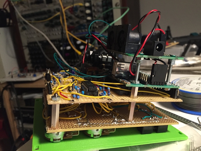
[Need Help with SPI] Euxoloti for axoloti (Eurorack Module)

modular

#1

Hi everyone,
I started a thread about CV input circuit for axoloti core at the google group but I had less time to work it out.
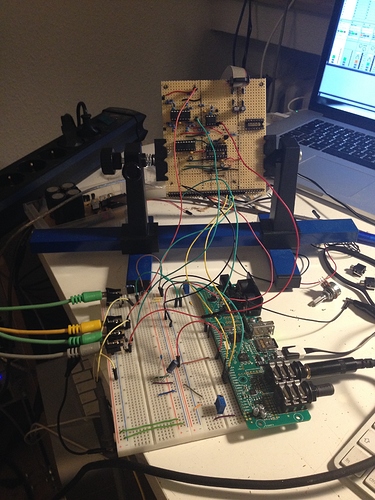
The last days, I have worked out some pcb designs. The current axoloti eagle files aren't online. My current pcb design is for the stm32f4 disco board but I will change it, if the axoloti files are online.

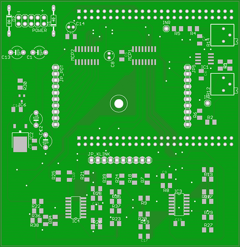
Can someone can help me with some software things? Does the MCP3208 CS/SHDN pin need a extra GPIO or can two MCPs use the NSS pin? I need to use two MCP3208 to read the analog voltages.
I want to use an OLED 128x64 display connect to I2C but which I2C port does axoloti fw use?
Will it possible to use encoders with axoloti? Where should I connect them?

SMD parts will be 1206 and SO-IC which are easy to solder.

Feature List:
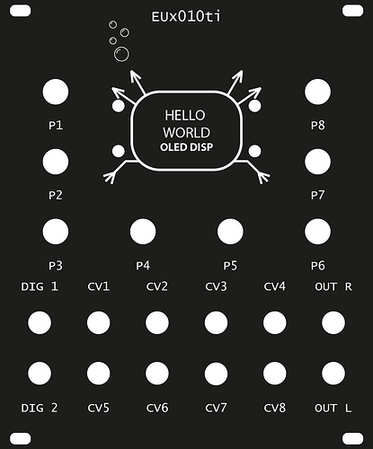
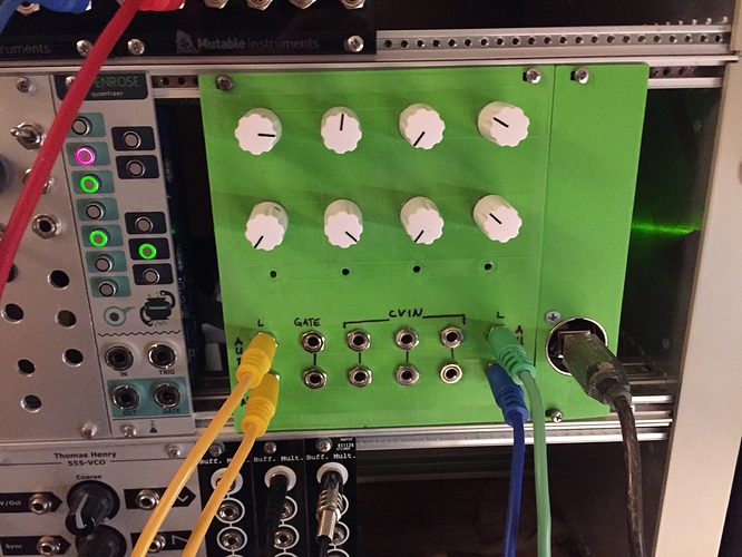
- 2 Digital Ins
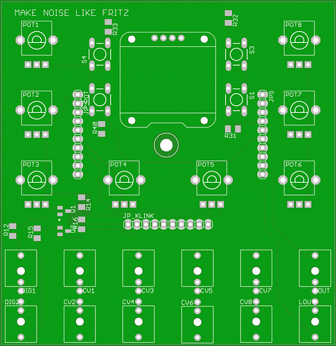
- 8 Pots
- 8 CV Ins (Range 0/5V or -5/+5V)
- 4 Pushbuttons
- 128x64 OLED Display

shematics:
https://drive.google.com/open?id=0ByIEww3RjUnNfnJoMENwbktrYmpOYlBqYUNqWWZRdFNDYUlNR0tsbHVwSzAyTjRfNm4xNE0

TOP PCB

BOTTOM PCB

20% transparent black Acryl Panel (Lasercut)


Euxoloti - Hardware version confusion!
Axoloti as EURORACK Module?
Using 5V peripherals on 3.3V axoloti
Audio-to-DC for gpio/analog/in: range?
#3

@Kalle
sorry, the link to shematic was broken. I fixed it.
https://drive.google.com/open?id=0ByIEww3RjUnNfnJoMENwbktrYmpOYlBqYUNqWWZRdFNDYUlNR0tsbHVwSzAyTjRfNm4xNE0

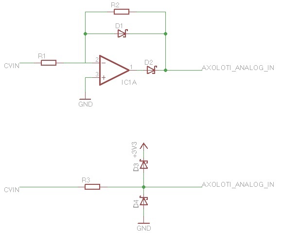
My layout scales CVs to 0/3V for the discoboard. Axoloti inputs accept 3.3V.

To scale the CV from 0/+5V to 0/3.3V replace R34 (60k) to 66.5k. For input of -5/+5V replace R34(60k) to 33k.
The MCP3208 has diode input protection. If you don't use a MCP3208 you have to add extra shottky diodes before the signal is received by axoloti pins.

Check out the old thread for more informations.
old thread CV: https://groups.google.com/forum/#!topic/axoloti-users/iAowfdL7Rxw


CV in to Axo analog in (gpio)
#4

Hey Paul.

Thx alot was just what i needed smile


#5

Is it just CV ins ? Why not out ? ( I don't know it is possible and I hope it is )
I also own a patchblocks and there is similar extension in engineering for it too

http://www.maker.ie/kits-patchblock/patchblocks


#6

at the moment, it's just cv ins…cv out is much easier. I don't try it with a stm32 but it should be similar to arduino world.

You can use a simple DAC (like MCP4921/MCP4922) or PWM + lowpass filters. Then use op amps to scale the output to your wanted signal level.

The EuroDuino Module use PWM + Filters (PAGE 2/2):
http://www.circuitabbey.com/files/EuroDuino_Main_Schematic.pdf

edit: it seems, that axoloti core has two DAC out (PB8 & PB9). There is a analog write module in the axoloti software.


#7

The PWM filter approach in Euroduino is bandwidth limited at 60Hz that is not a tight solution.
The two on-processor DAC outs are much better, 12 bit resolution, also 0-3.3V range. For full eurorack use this needs shifting+scaling.
An external SPI DAC is also possible.

The audio output is DC-coupled, while its voltage range is still much lower than eurorack, it can also be used for control.

Generally many approaches are possible, from a low-tech vactrol approach to high-precision drift free.


#8

oh, sorry for the disinformation.

Last night, I tried some DAC ICs (MCP4x22) and it's working. The bitshift operation is not the best solution but maybe a good starting point.

Patch (edited): spi mcp4x22.axp (4.0 KB)


#9

Take care, Paul, you're using an uninitialized pointer in your script, that could cause weird side-effects,
and you have to use a memory section suitable for DMA for SPI communication.
Check archive/tests/io/spi_lkm1638.axh for an example.


#10

thank you johannes. I checked the whole archive/test/Io spi examples. It helps much to understand, how to get spi running and communicate to other devices. Are there any more I2C examples? I'm trying to connect MPR121 touch sensor and can't get it working.

What do you and the others think about a database, where user can share their patches and objects etc. like www.maxforlive.com?

here is a fixed version of script object. Is it now correct or are there any misstakes?

// by paul for axoloti script2 objekt.

// inlet1 = DACout A
// inlet2 = DACout B

uint8_t *txbuf;

void setup(void){

static uint8_t _txbuf[32] __attribute__ ((section (".sram2")));
txbuf = _txbuf;

}

void loop(void){
//MCP4922 DAC (MCP4822: Bit 14 is ignored)
// dacA: 0x7 (Bits: 0111)= select output A, Buffer enable, Gain *1, SHDN (active mode operation) + 12bit Value of in1
// dacB: 0xF (Bits: 1111)= select output A, Buffer enable, Gain *1, SHDN (active mode operation) + 12bit Value of in2

uint16_t dacOutA = (0x7 << 12) | ( in1>>15 );
uint16_t dacOutB = (0xF << 12) | ( in2>>15 );

spiSelect(&SPID1);
txbuf[0] = (dacOutA >> 8);
txbuf[1] = (dacOutA & 0xFF);
spiSend(&SPID1,2,txbuf);
spiUnselect(&SPID1);

spiSelect(&SPID1);
txbuf[0] = (dacOutB >> 8);
txbuf[1] = (dacOutB & 0xFF);
spiSend(&SPID1,2,txbuf);
spiUnselect(&SPID1);

chThdSleepMilliseconds(1);

}


#11

Code looks good.
I have no I2C examples available that I'm certain to work currently. If your sensor does not respond, maybe check with an oscilloscope or logic analyzer if you seen any traffic?


#12

hi everyone,
today I tested the cv ins of the prototyp. cv & gate in are working perfectly. the circuit is the same as posted in the first post.


demonstration video: https://youtu.be/tmKdikNo2ys


#13

GREAT GREAT GREAT smiley haha so we can almost assume clocks works aswell smile wink smiley


#14

si, it reminded me of mario world.
Next thing will be audio in/out.


#15

Ahh come on my sweet little board smile im getting more and more hooked smiley


#16

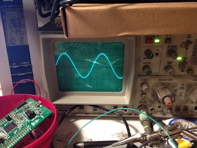
audio in/out needed some modification. I will update the schematic in the upcoming days. Now it's running very sweet and I love is little board more and more. audio out ist eurorack compatible 10V p-t-p. audio in needs a dc-coupled input (10uF elko) to filter DC offset.

Tomorrow, I will post a sound example.
After all, I think, I will add some extension headers to add e.g. some shift reg. for a clock divider etc…

audio out from axoloti core (10V p-t-p) - sin example:


#17

the euxoloti prototyp runs great. The code for the two mcp3208 needs some improvements.
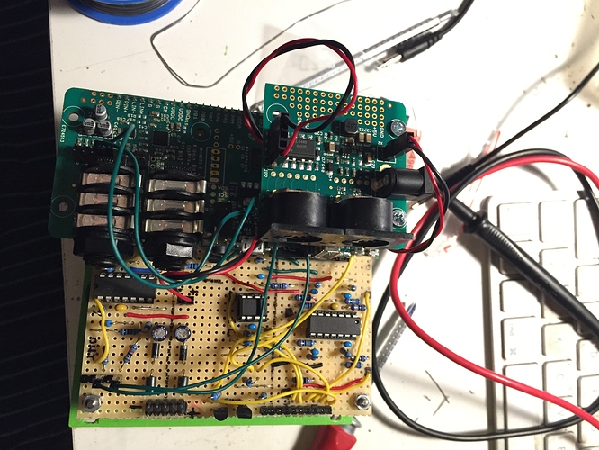
Here are some pics and a quick sound demo

Patch: Ableton MIDI OUT -> MI CVPAL -> MI Braids (CSAW) -> EUXOLOTI -> Audiointerface
Sounddemo (wav, 96khz, 24bit)


#18

Im surprised you didnt mount the axoloti connections to the front panel...
Id have thought the midi din/usb and SDcard could all still be very useful in a modular environment - no?


#19

yes, this would be an other option and can be easily realized. If axoloti eagle files are online, I get the right measurements and print a new panel with axoloti connections on the panel.
First, I want to get the whole eurorack stuff (audio in/out, cvs) up and running. The MIDI/power pcb part should be mounted at the extension panel, but as johannes mentions that it would be better to use the original external power pcb for powering the axoloti instead of a 7805 circuit.
I'm doing the whole thing very cautious. I don't want to break my axoloti, because I only have one and to get a new one will take a long time wink


#20

Any news on this? Its a very interesting thing for me, as I am beginning in eurorack, and would love to be able to use my Axolotis with other CV enabled things :>


#21

Hi Paul. I'm new in the group (and my Core board hasn't arrived yet), so I'm catching up on what you've been doing. I'm also interested to integrate Axoloti with Eurorack. btw, I design some modules including this one coming from 4ms. http://www.4mspedals.com/p.php?p=709.

You've been quiet since August. Is the project active now? I know how these things can go.
Cheers.!