Mongiloti Synth


#1

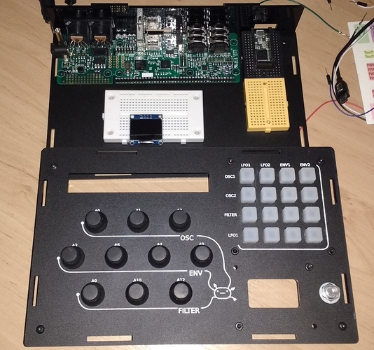
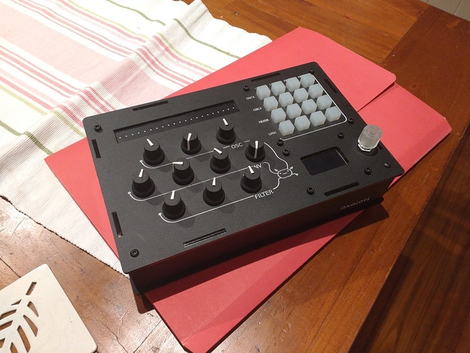
May I present the oft mentioned Mongiloti synth currently in progress (and has been for a while now). I thought it better to make a thread for it to keep up momentum.

Features

  • One Axoloti (natch)
  • Teensy 3.2 for all state and midi control
  • Adafruit Trellis for mod matrix (i2c)
  • 10 Pots
  • 1.3" OLED (i2c)
  • Sparkfun RGB lit encoder.
  • SD Card for state and preset saving.
  • Force Sensitive Resistive strip for anything I want.

Wiring
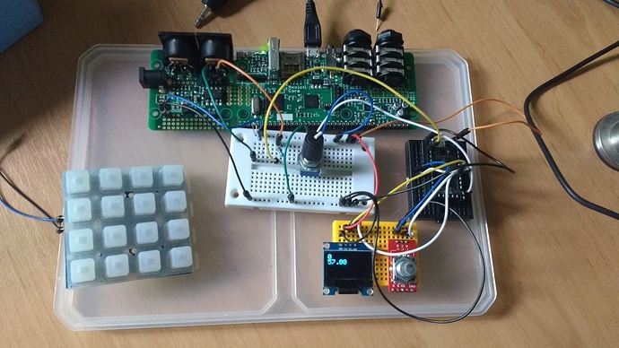
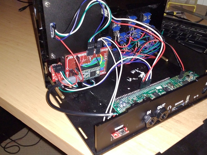
The Teensy sends CC for parameter control via headers soldered onto the back of the Axo's Midi IN socket. Everything else, including the FSR is wired to the Teensy. All components have been proven against a simple patch and I'm quite happy with the results.

I discovered the Trellis right after the Arturia Matrixbrute came out and I had to have it for a micro-mod matrix.

Software
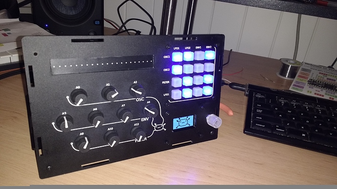
Back in January I had a very elaborate patch already built. Multiple OSC's, FX and the Mod matrix worked out. I then got distracted building a Midibox and since then the community has moved on bringing out fabulous modules that I just must have included. I also realised that my previous design of having more fixed controls meant the underlying patch would be constraints as well. So the patch was scrapped and the panel design made more flexible. I reduced the knobs to only those controls used for live sound shaping and instead of havibng "OSC1", OSC2 etc, I've got a OSC section with 3 blank knobs. Likewise ENV and Filter sections with just blank knobs ready to be mapped via the Teensy software.

All other parameters, LFO's and FX's and such like as accessed through the menu shown on the OLED along with preset saving and perhaps even mapping controls to save me compiling everytime I reassign a parameter.

One other Brucie Bonus I found was Tinyscope. Again, I found this right after the Korg Minilogue came out and had to have it.

Build Status
Waiting on parts to finish the wiring. There's a stack of wires in this little box and I want it nice and neat. The Teensy software has been started and the patch is empty. Midiboxes aren't good for getting other things done. :slight_smile:

Source
Everything, design files, SVG's, Arduino software and patches will be on Github.


SPI/I2C OLED display
Extra midi io via UART not working in standalone mode
#2

Currently I'm wiring everything up. The trouble with browsing sites like Sparkfun is you end up with major project scope creep as you find all sorts of nifty doodah's that would look lovely on a little DIY synth project. Everything doodah means more design, testing, wiring and most of all coding. The result is the physical build takes much longer.

I was testing the Midi channel from Teensy to Axo last night and found a big issue. I had soldered a little header behind the MIDI IN socket and was pushing CC from the Teensy serial. This works great. I then parallel tested by driving the Axo from my Midibox while knob twiddling from the Teensy. Operationally this works fine. This axo doesn't care where signals come from but as soon I play the Midibox I get big signal induction into my speakers with a lovely tickblurbblargwhumpwhum along with the playing sequence. Even with the mixer turned off. Ugly.

Lots of wire waggling, moving stuff around, plugging unplugging later and I realise it's the 5v signal I'm backfeeding from teh Axo 5v header into teh Midi socket to complete the circuit. Turning the Axo into a giant inductor. My Teensy and all components are also fed from the Axo 5v so I had no way to isolate the problem.

Removing the 5v from the Midi header solved the feedback but it was getting late and I didn't notice if Midi still worked without it. Probably not.

To solve this I'm reverting to Hugo's GPIO midi patch and use GPIO instead.


#3

Hugo's patch example contained a great fix. Using the Midi IN objects from Hugo's patch, I connected my Teensy TX -> 220Ohm Resister -> PA3 on the Axo. Wallah, instant MIDI in without any interferance on the external socket. Niiice.


Axoloti w/Teensy
#4

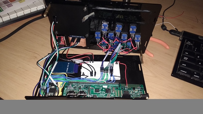
Lovely wires. I still have the FSR to wire up but I'm not sure where to put it. My only analogue pin free is 14 which is also my DAC. I was hoping to keep that for Tinyscope. The alternative is taking the Teensy out and breaking out a pin underneath. Not a good idea really. The little fella is a bit stuck in there now.

It Lives!


#5

It's amazing how projects take a step back. I look at that picture above with all the neat wiring and wonder wtf happened to my life. :slight_smile:

Turns out I couldn't close the case! After a bunch of rerouting and rewiring I'm quite unhappy with using pluggable headers and breadboards. This is something that's meant to be closed and never opened again so back to the drawing board (or application) for an internal redesign. This time the components will be soldered onto a stripboard to reduce the amount of fly wires and unsoldered connectors.


#6

Tiny protoboards ordered. Currently the Teensy sits behind the Axo at the rear of the case on the bottom panel which means all the wires are going from the top panel to the back panel. Not a good design choice. The back panel has a hole to access the Teensy USB port for programming (Teensy is powered from the Axo 5v).

I've got a new bare teensy with low profile pins to stick on the protoboard which will be mounted under the OLED or FSR on the top panel instead. I can then route and solder all the wires without involving the bottom at all. Much easier and neater. To access the USB board I have a tiny USB breakout which will be mounted at the back.

So in the end I'll have the 20+ wires to the Teensy solder and routing nicely with solid core and the wires stretching to the bottom are the 2 wires to the Axo (PA2&PA3) and the USB.

Or I might do nothing and go make some music instead. :smiley:


#7

Hardware finished!!!

To solve the wiring mess I built a little daughter board from a protoboard. With this design I could breakout all the pins of the Teensy (basically every top side pin available) into header sockets and pin arrays. This daughterboard, which laughably now looks just like a RaspberryPi, is mounted on the pins of the OLED. This reduces the wire count and by coincidence the protoboard mounting holes almost line up with my OLED case mount screws (very very slight squiff oled screen results).

The main benefit of this approach is the majority of components, and the Teensy are all mounted on the top panel. Reducing the bottom to top panel connections to 4 cables which easily plugin.

The Teensy USB VIN is disconnected (see Teensy site) so everything is powered from the Axoloti. To access the Teensy USB for programming I used a little Sparkfun USB breakout board. You can see it sticking out the back as the case design wasn't built for this. I used some acrylic glue to stick it in there. In that Teensy hole is also a "Program" tactile switch wired to the Program pin on they teensy.

The Force Resistive Strip (Interlink 4" FSR) needed 2 Digital GPIO and 2 ADC to measure both distance and pressure. My intention for this is a quick keyboard style strip for testing sounds as I knob twiddle. However, I've ran out of ADC's on the topside of the Teensy and can't be bothered engineering access to the bottom pads which can be difficult. So the FSR is wired directly to the Axoloti and I'll need to work out how to tame it within the patch.

At present I have a barebones Teensy sketch that proofs all components as working and sends Filter CC's only. My Axo patch is a skeleton as I decide what to include as a first cut. With SSS's prolific module frenzy I look forward to developing the Mongiloti into a flexible beast of a synth.

P.S. Forgot to insert the little MicroSD breakout before closing it up. Argh!


USB Midi Controllers
#8

Bit of a status update.

In order to finish this project I've settled on a fairly ordinary patch design. 3 OSC's with standard types, 2 LFO's, 2 ENV's and 3 FX if possible. Now this doesn't fit onefunctionperknob style onto my panel so I need a bit of Menu diving and that's where I'm going slow. I use Atom and PlatformIO to develop on the Teensy and being an ex c++ hobby game devver my c++ design's always get overblown. Component Object models, single functional classes, state machines are all previous skills. Arduino isn't like that though, it has setup() and loop(). You need global to hold state (Heresy!!!) and can't use "new" or bears come and get you.
I'm really struggling keeping it simple :). Really, all I need is a array of menu structs holding CC"s and some labels but somehow I keep almost writing HAL 9000's everytime I touch the keyboard. :slight_smile:

Also busted the top half of my Oled, it gives little lines and I remember chipping the pcb a wee bit last time it was opened. One day, I shall finish this and do a video. :slight_smile:


#9

Outstanding!!! I am a newbie here and thinking of a similar project using the teentsy 3.6 so let me get this right ... before I blow up any parts...you are using the high speed USB as as the ONLY cool ... but I can't seem to find out your pin out connection list from the axolotl to the teensy.


#10

The only connections between the Teensy and Axo are the UART for Midi control and power. My docs show the pinout (I admit it's confusing looking, I should tidy it up).

In reality only Teensy TX to Axo PA3 is needed to send Midi but I've wired up the RX as well. Power is taken from one of the many Axo 5v headers.

Note that a USB 5v generally can't supply both the Axo, Teensy all the pots and the OLED with enough power. I use a 1A DC power supply.


#11

I see it and will make sure that I will keep the pin location and count when I get further in my design so we can all take advantage of software created with few mods.... one more question ... as far as range of selectivity and performance latency are you satisfied with midi over standard serial?


#12

Hey that's a really nice project, both technical and design wise!

Do you also send midi from the axoloti back to the teensy? I'm interested in midi over serial between two axoloti boards via PA2/PA3 but find it not so easy to use Hugo's script as a non coder, so if you have some examples it would be great if you could share them :slight_smile:


#13

Midi over serial is fine until do filter sweeps then it jumps. I haven't optimised my Pot code yet though and I plan to switch to 12bit for that one if I can't fix it. It'll never be as smooth as a GPIO connected pot though. For everything else it seems fine.

Haven't tried data the other way yet. Still struggling with bad code. :slight_smile:


#14

we'r all in it together... yes it looks from the posts you are having a classic windowing problem ... but that's just a SWAG from an old data com person.... it seems to be a java state machine over the little usb port ... I will be hanging with a friend over the holidays who has been dealing that to drive the big led road information signs for the past few years


#15

Hello, someone can plan to make a mongiloti kit? The project is finished and ready? I have two unused axoloti and I want to build a pair of mongiloti.
Thanks


#16

Not finished and no plans for a kit. The case files, BOM and pinout are on Github but I've rewritten the Teensy code 3 times now and I'm still not happy so will be starting again. Since i've started building an Ambika my Synth needs are covered so I'm looking at the Axo for wierd things and effects instead. Which means I need to further genericise the controller firmware. It sits on my desk looking nice and used for an occasional PC connected patch.


#17

Thank you for your reply.


#18

what a great build. As a newb and also trying to 'define' what I want out my my new controller build, I really appreciate your detailed explanations of yours. Lot's of great info as I've also been looking at the teensy and/or mux the analog.


#19

great info in that comment, Thx a bunch!


#20

How did you managed to get the tx and rx working from teensy to axo? I feel like im very close but something is still missing. Did you change the hugos patch with teensy?