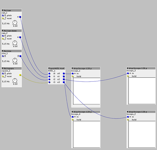
[GPIO I/O] Example 4051 de/multiplexer reads 8 analog sources


#21

Hi Paul,
could you sketch up an example how to write to the 4051's pins,
instead of reading them?
I want to multiplex the Axoloti's 2 analog outputs (PA4 + PA5),
in order to create a simple control-rate patching matrix...

I'm all new to the Axoloti and c-scripting as well,I understand some parts
of your script but not enough...

cheers

Robert


#22

hi @rbrt ,

sorry, I'm not at home so I can't test the following code example.

You want to route the DAC1 output to any Y output pin of the 4051 like this:

axoloti Patch: 4051 DAC out PA4,5.axp (2.8 KB)
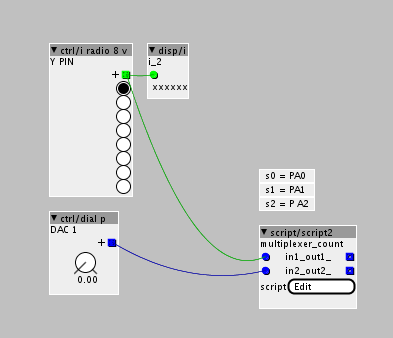
some parts of the code are from the "./out/analog.axo" object. An other solution will be to use a separate "./out/analog.axo" object and the script object only controls the Y pins of the 4051.

SCRIPT OBJECT CODE:

/*
marked comments with "*" are from axoloti "script" object
code isn't tested
*/

int i; // select y-input

void setup(void){
palSetPadMode(GPIOA,0,PAL_MODE_OUTPUT_PUSHPULL); // s0 Pin of 4051
palSetPadMode(GPIOA,1,PAL_MODE_OUTPUT_PUSHPULL); // S1 Pin of 4051
palSetPadMode(GPIOA,2,PAL_MODE_OUTPUT_PUSHPULL); // s2 Pin of 4051

palSetPadMode(GPIOA, 4, PAL_MODE_INPUT_ANALOG);		// DAC OUTPUT PA4*
palSetPadMode(GPIOA, 5, PAL_MODE_INPUT_ANALOG);		// DAC OUTPUT PA5*

RCC->APB1ENR |= 0x20000000; // *
DAC->CR |= 0x00030003; // *

i = 0;

}

void loop(void){

i = in1;		//script object in1 controls 4051's Y output selection
if (i == 8) {
	i = 0;
}


palWritePad(GPIOA,0,((i& 0x01) > 0));		// write s0
palWritePad(GPIOA,1,(((i>>1)& 0x01) > 0));	// write s1
palWritePad(GPIOA,2,(((i>>2)& 0x01) > 0));	// write s2


// select pin of the 4051 and route the DAC output value to it.
switch (i){
	case 0: 	
		DAC->DHR12R1 = in2>>15;				// check "input 1" of the "script" object and control DAC PA4 *
		/*DAC->DHR12R2 = in2>>15;				// check "input 2" of the "script" object and control DAC PA5* */
	break;
}


chThdSleepMilliseconds(5);	// short delay

}

I hope this may help you.


#23

Hi Paul,
thanks a lot for the inspiration!
looks like right now I'm rather stuck with my little project:

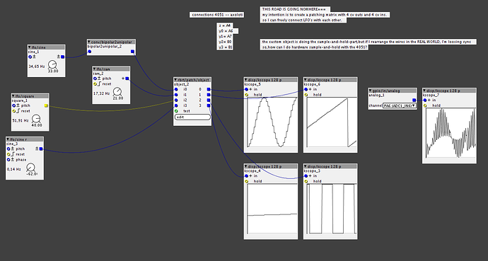
My intention is to build a 'hardware' patching-matrix using REAL WIRES,
something like 4-8 analog outputs and inputs..

so, I've been attempting to multiplex the axo's A4 analog output with the 4051.
I actually got there, but I need to sample and hold the 4051's outputs somehow.
right now this is done inside the custom object I wrote
(you need the 1.07 release version to run the patch!!)

but once I rearrange them WIRES in the REAL WORLD, it's all loosing sync...
so, do you have any idea about how to sample and hold the 4051's outputs?


ah,you have to wire things up like this:
(I'm referring to your first post)
z = A4
y0 = A6
y1= A7
y2=B0
y3 =B1

4051 multiplexing.axp (7.3 KB)


#24

I deleted the axoloti 1.0.7 version and I'm using the stable version 1.0.6. Can you upload your axo object here, so I can watch your object code.
do you have used an array to store/recall PA4 write values?


#25

Here you go with the object!

4051_multiplexer.axo (2.2 KB)

it gives me some errors because of incorrect HASH (?!) and other weird things...

no,it's not using an array..it's simply muxing/demuxing..

but hey,an array might be a good idea for a totally diffrent (kind of fake..) approach...
where the wires wouldn't actually transmitting anything but merely act as switches..
of course,then it's not possible to connect multiple devices..


#26

ok, there were some errors. I haven't checked, if the following code is working correctly:

http://pastebin.com/YVnng4bf

4051_multiplexer.axo (2.6 KB)

but you will need a hardware S&H circuit to buffer each voltage of 4051 outputs? rvense works on a similr project.


#27

Did you have any success with this? I would like to use the axoloti as brain for a 64 input midi controller, but i dont want to order any board until people actually are having succes with multiplexers/multiple inputs. And most importantly: I need a blueprint i can follow, since i dont know how to do any coding!
Thanks:)


Using axoloti as a midi controller brain?
#28

hi @the19thbear
the 4051 example from the first post is working. I didn't know, if the last thing for rbrt is also working. He didn't post a feedback.

Do you know the "ainser64" module from the ucapps site? It only needs a trace mod for one CS pin and a 3,3V vreg instead of the 5V vreg…It's maybe possible do use the "ainser64" without the CS mod but I didn't get it working. One of their main core is based on stm32 disco board. So it also should work with axoloti.


#29

Thanks. So do i only need the ainser64 module? or do i need any other modules? And you are saying that i can connect that to axoloti? Sorry im new to all this:) I know about soldering/reparing analog synths, but coding/the inside parts of midi is new to me:)


#30

Anything's possible with a little code!

Look at the schematic:

The AINSER uses an SPI 8-channel ADC from Microchip (MCP3208). It then connects to each of the inputs on that 8-way multiplexers, 4051, like in the example above. The multiplexers allow you to route one of eight sources to a single input by setting three pins on the chip. Using some software to control the multiplexers, you can select which eight pots go to the inputs of the ADC. So you need to write a scanning routine that counts from 0-7 to select an input on the multiplexer, reading from the ADC at each count. There's another thread here that shows how to use that exact same ADC, actually.

Due to the flexible design of MIDIBox, the AINSER module uses a shift register for the control signals but this is not strictly necessary. You could just connect three GPIO from 'loti to where the outputs from the shift register would go and set those GPIO directly.


#31

Sorry again, but what schematic are you referring to?:smile:


#32

thanks @rvense for detail explanation.
@the19thbear I think rvense talked about the ainser64 schematc here.
the MCP3208 and 595 are sharing the same CS pin… the following examples need a single CS for each SPI IC…
MCP3208 example
74HC595 example

To get single CS, you have to do a trace cut and route to a new header on J2 or J3.

Hope this helps a bit.


#33

Thanks:) I'll look into it.


#34

Hello there,

Im still a noob especially with electronics,i just received some 4051's and I see in the first picture, that if you use the 4051 you loose 3 gpio's,pa0,pa1,pa2.
Is it possible to use only one gpio?


#35

You need 3 bits to count to from 0 - 7.. to designate the input source, then you need a pin to read the value.


#36

Hmmm i think i understand, so you use more gpio's , thats a bummer! Then I'm most likely still many gpio's short. Maybe i must think of a teensy board to make around 32 extra midi buttons.
I need to have 10 pot meters hooked up straight to the axoloti.some rotary switches (with resistors) , and then a lot of demuxed pot meters.i see this is not possible if you need 4gpio's for one 4051.


#37

You can connect the same GPIOs to the select signals of several 4051s. Just connect their outputs to different ADC inputs. A single eight channel ADC like the MCP3208 would allow you to scan 64 pots.

With one extra GPIO for an additional SPI chip select signal, you should be able to use a second ADC. So that's 128 analogue inputs with the SPI lines and six GPIO :slight_smile:

There's some more info here on this approach as used in the MIDIBox project: http://ucapps.de/mbhp_ainser64.html


#38

Ok,i will try this approach if i get it correct. I still have some soldering to do and have to compile the patch, mostly cut and paste from other patches so that's is ok. I will be back!:grinning:


#39

You could use a counter IC (4520?).. http://electronicsclub.info/cmos.htm#counters


#40

Sorry bout the bump.
Would you happen to have an example patch for a 16 input multiplexer?
I own a couple of these https://www.sparkfun.com/products/9056 and really want to use them to add some inputs to my axoloti. Your example is super similar to what im trying to accomplish but I have an extra S pin on my breakout board and I'm not sure if the script needs to be modified to work with this multiplexer.

Edit: Nevermind, I've started a new thread on the matter, sorry all!