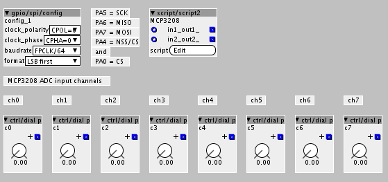
[GPIO I/O] Example ADC MCP3208 & SPI


#1

Hi everyone,
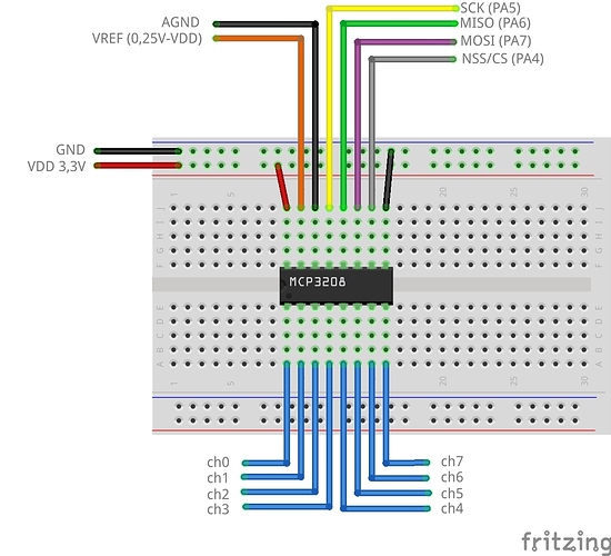
this example should show, how a MCP3208 can be used to read eight analog sources. The MCP3208 is connected to axoloti SPI port. This ADC method is much faster then the 4051 method and the MCP3208 has an input protection. Each ADC channel has a 12bit resolution and is compared to the VREF voltage. VREF should be in a range of 0,25V to VDD and decoupled/stabilized by a 100nF capacitor and min. 10uF polarized capacitor (not shown in the wiring picture). If you want to use more then one SPI device, be sure to disable the CS pins of the unused devices. CS Pin can be controlled by axoloti NSS(PA4) or any other digital out GPIO pin.

The bits are send by LSB and read each single analog input channel. By changing the Single/Diff bit (bit 7 of the first byte) you will get the differential between e.g. CH0+ and CH1- etc.. Check page 19 f. of the MCP3208 datasheet.

Patch: MCP3208 single channel:
mcp3208 signle channel example.axp (5.9 KB)
Script code

Wiring (without caps)


How to get a maximum of knobs on a axoloti core?
[GPIO I/O] Example 4051 de/multiplexer reads 8 analog sources
Adding more analog inputs using a multiplex breakout board
Semi-modular hardware patch bay?
#2

Thanks for the thorough writeup. I'm trying out this circuit with an MCP3008 and it seems to work pretty well. I don't fully understand the bit about decoupling VREF (and don't have right caps to try it at the moment), but I assume that would mostly improve stability and accuracy of measurement.

I do have a couple questions that you might be able to help me get through. First, the dials always max out at a value of 3.97 (out of 64.00) rather than turning through their full range. Is this a function of the 12-bit depth of the ADC or perhaps my VREF is out of scale? I'm using some 10k pots I had laying around, seemed to work fine in full-range when used on the analog in pins of axoloti.

Second, I'd like to pair this with the MCP23S17 circuit I've built for my seven-segment display, but it looks like that chip uses MSB-first format and this one LSB-first. Is it possible to run them both simultaneously? (perhaps using 2 spi/config objects?) Or should I find another ADC chip that works on the same SPI format?

Finally, in multi-device configurations, is one digital pad on axoloti needed for each chip in addition to the SPI pads (to manage the chip select on/offs)? I assume the answer is yes, but I'd like to figure out how many pins I'll need on the connector between my control board and axoloti to avoid extra bodge wires.

Thanks again for your clear and cogent demos.


#3

I had a closer look at some of the code used for SPI configuration and it seems like this would be theoretically possible, but maybe not with the provided objects. For example, the gpio/spi/config object initializes a named static "spicfg" constant that would conflict other config objects.

Nonetheless, ChibiOS does support sequential spiStart() calls with different config objects, according to this thread:
http://forum.chibios.org/phpbb/viewtopic.php?f=2&t=676

An example is given as:

if ( SPID1.config != &config1 )   
spiStart(&SPID1, &config1);
spiSelect(&SPID1);
// transfer to device #1
spiUnselect(&SPID1);

// new peripheral
if ( SPID1.config != &config2 )   
spiStart(&SPID1, &config2);
spiSelect(&SPID1);
// transfer to device #2
spiUnselect(&SPID1);

If I have time tomorrow I might hook up both chips and have a quick test to see if doing this manually in a script/object would work.


#4

Talking to myself here, but here's some info for anyone else trying this. I dove into it this evening and determined that it is possible to use multiple SPI devices & formats in the same patch. The built-in gpio/spi/config object instantiates its own configuration, but this can be overridden by creating new SPIConfig objects and calling spiStop(&SPID1) then spiStart(&SPID, &your_config_here). Here's an abridged version of some working code to read from my MCP3008 and write to the MCP23S17 with this technique. (here be dragons)

uint8_t *txbuf;
uint8_t *rxbuf;
const SPIConfig spicfg_a = {NULL, GPIOA, 4, 3<<3}; //MCP23S17 takes MSB first, uses standard axoloti Chip Select pin PA4
const SPIConfig spicfg_b = {NULL, GPIOA, 0, 3<<3 | SPI_CR1_LSBFIRST}; //MCP3008 takes LSB first, uses extra Chip Select pin PA0


void setup(void){
    spiStop(&SPID1);
    ...
    palSetPadMode(GPIOA,0,PAL_MODE_OUTPUT_PUSHPULL);    // MCP3208
    palWritePad(GPIOA,0,1);                 // pull high to disable first MCP3208
}


void loop(void){
    palWritePad(GPIOA,0,1);        // disable MCP3208
    palWritePad(GPIOA,4,0);        // enable MCP23S17
    spiStop(&SPID1);
    spiStart(&SPID1, &spicfg_a);   // load appropriate config
    spiSelect(&SPID1);
    txbuf[0] = SPI_SLAVE_ID | ((SPI_SLAVE_ADDR << 1) & 0x0E)| SPI_SLAVE_WRITE;
    txbuf[1] = 0x12;               // gpioa address
    txbuf[2] = 0x01010101;         // binary data for each pin on/off
    spiSend(&SPID1,3, txbuf);  
    spiUnselect(&SPID1);
    palWritePad(GPIOA,4,1);        // disable MCP23S17


    zxbuf[0] = 0b01100000;
    zxbuf[1] = 0b00000000;
    txbuf[2] = 0b00000000;


    palWritePad(GPIOA,0,0);     // enable MCP3208
    spiStop(&SPID1);
    spiStart(&SPID1, &spicfg_b);// load other config
    spiSelect(&SPID1);          // START SPI

    spiSend(&SPID1,3,txbuf);    // send SPI data zxbuf[]
    spiReceive(&SPID1,3,rxbuf); // receive SPI data from MCP3208
    spiUnselect(&SPID1);        // STOP SPI
    palWritePad(GPIOA,0,1);     // disable MCP3208
            
    int z = (rxbuf[1] << 8| rxbuf[0]) << 20;

    if (pin == 0){
        PExParameterChange(&parent->PExch[PARAM_INDEX_c0_value],z,0xFFFD);
    }

    chThdSleepMilliseconds(1);
}

#5

The SPI slave select signal can probably be shared when the MCP23S17 and MCP3008 have different SPI addresses.


#6

Hi @paul,

wrong wiring diagram, see discussion below for correct diagram

Thanks for the example, and sorry for the noob question:
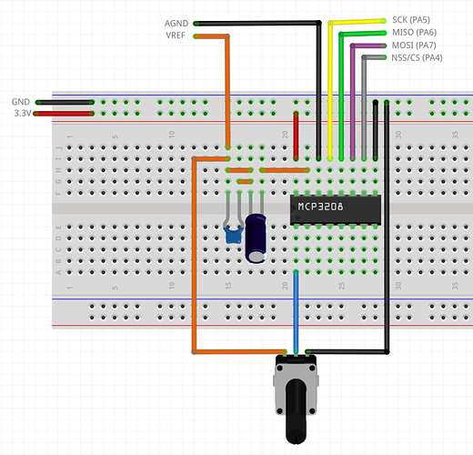
Is this how you would decouple/stabilize an MCP3208? Just got mine in the mail, they're quite pricey, don't want to fry them straight away :smile:
Also is this how you would wire up a pot to CH0?


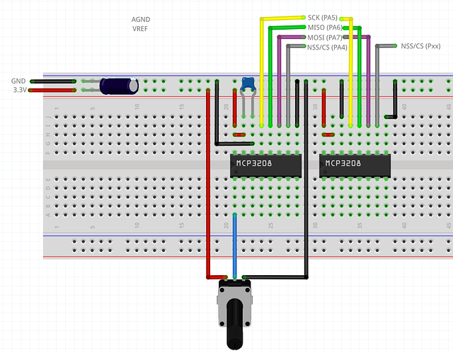
Also I would like to put another MCP3208 next to this, to get 16 input channels seeing @matthewcieplak example, it seems to be possible, but how do I wire it? do they share all but one pin? my bet is the SCK pin is to be connected to another PA pin on the Axoloti...

Thanks!


#7

The wiring on the potentiometer in your diagram looks fine. The chip will compare the voltage coming in to the input (from the middle pin on the pot) to the voltage coming in from VREF (pin 1 or 2 IIRC).

Your capacitors/decoupling setup looks strange. The small cap is wired in series with the large, and it seems to be bypassed by a jumper. The large cap is between the chip and the VREF, which will block DC altogether (meaning you'll end up with a VREF equal to the leakage of the capacitor, or a few microvolts).

Instead, you should wire your decoupling caps across the positive voltage source and ground. They don't allow current to pass through, so they won't short your system, but they will store a charge that will fill in the gaps or dips in power on your 3.3v source. I wired 3.3v to pins 1 and 2, (PWR and VREF) and ground to 3 and 8 (GND and AGND), and then put a small 100nf (0.1uf) cap directly between pins 2 and 3. You want it to be physically close to the chip as you can get it on the board (within a few cm). I also have a larger 10uf (polarized) capacitor between 3.3v and GND near my input terminal that serves all the chips on the board.


#8

To add an additional MCP3208, it will share all the same connections (3.3v, GND, SCK, MISO, MOSI) except NSS/CS. That stands for "not slave select"/"chip select." So you will need to spare another PA pin from Axoloti (one for each chip basically) as a digital output. Pull it high to disable the chip, low to enable it. Only one CS output should be low at any given time, so you can read the inputs from one chip at a time.

As johannes mentioned, some chips have SPI addressing via bias pins (like the MCP23S17) so you could share the CS pin on up to 8 separate chips, but I don't think that's a feature on MCP3008/3208, so I'd start by separating it.


#9

hi kaos,
what matthewcieplak writed is right. There is a error at the wiring picture.

If you want more than 8 input by one mcp3208 you can check ucapps AINSER 64 module .
It uses a mcp3208, 74hc595 and some 4051 multiplexer. The mcp3208 and 74hc595 use the same NSS/CS pin. I get it working by disconnect the NSS pin of the 74hc595 and connected it to separate NSS pin and powered the AINSER64 it from an external power source.
The other DIN and DOUT Moduls are working without any modifications.

It would be great if someone get this Module working with shared NSS pin.


#10

allright, going for this now. Thanks for the input


#11

@matthewcieplak, I did all the soldering as you mentioned and as I described and while it worked for one MCP3208 I'm making some mistake for the second. I think and hope it is on the software side. @paul, your script comment mentions:

Connect the MCP3208 CS pin to the NSS(PA4) or any other digital out pin of axoloti.
In this example, the MCP3208 CS pin is connected to axoloti B0(GPIOB,0) pin.

but in the code I have the feeling you're using different pins

palWritePad(GPIOA,0,0); // enable MCP3208

this is the NSS/CS pin right?

While I'm using the pins labeled PA4 for the first and PA3 for the second one I soldered, My guess is I should use

palWritePad(GPIOA,4,0);

to enable the first one and

palWritePad(GPIOA,3,0);

to enable the second one

the strange thing is, that this worked when I copy-pasted your code using palWritePad(GPIOA,0,0);
This does not make sense as in my opinion, nothing is connected to that pin...

What am I missing?

Kasper


#12

this was what I was missing.. you need to use the "alternate config" thing

I got it working for one device allready, now I will try it for the second


#13

Ok I'm hoping this is a software problem. I get accurate readings on 16 pots using 2 MCP3208 if, and here's the catch...

I always get accurate readings from MCP3208 #1, the one connected to axoloti PA4
I only get accurate readings from MCP3208 #2, connected to PA3 if the pot on the same pin number on the other MCP3208 is turned to the maximum, otherwise I get some sort of average. If I turn the pot down, I get no reading at all..
I'm guessing somewhere in my script I multiply the values,
- but I reinitialised the vars,
- I increased the sleeptime between polling (thought it was some overflow)
- I renamed the z var in the second loop

It took me quite a while to figure out why everything was dancing and then not, I thought it was hardware, so I resoldered a lot of things... apparently for nothing, or not? a bit puzzled.

below is my version of the script

/*
MCP3208 script2 code
by paul
adapted by kaos, this script is not working, there is problem...

Connect the MCP3208 CS pin to the NSS(PA4) or any other digital out pin of axoloti.
In this example, the MCP3208 CS pin is connected to axoloti B0(GPIOB,0) pin.

If you use more then one spi device, it's importent to disable every other spi device by switching their cs pin. 
*/

uint8_t *txbuf;
uint8_t *rxbuf;
const SPIConfig spicfg_a = {NULL, GPIOA, 4, 3<<3  | SPI_CR1_LSBFIRST }; //MCP3208 pin PA4
const SPIConfig spicfg_b = {NULL, GPIOA, 3, 3<<3  | SPI_CR1_LSBFIRST }; //MCP3208 pin PA3


void setup(void){
	static uint8_t _txbuf[8] __attribute__ ((section (".sram2")));
	static uint8_t _rxbuf[8] __attribute__ ((section (".sram2")));
	txbuf = _txbuf;
	rxbuf = _rxbuf;

	palSetPadMode(GPIOA,4,PAL_MODE_OUTPUT_PUSHPULL);	// MCP3208
	palSetPadMode(GPIOA,3,PAL_MODE_OUTPUT_PUSHPULL);	// MCP3208
	//changes
	palWritePad(GPIOA,4,1);								// pull high to disable first MCP3208
	palWritePad(GPIOA,3,1);								// pull high to disable second MCP3208
}

void loop(void){
	// txtbuf[0] = txtbuf[1] = txtbuf[2] = 0b00000000;
   	txbuf[2] = 0b00000000;
 	
    	for(int pin=0; pin<8; pin++){
 
	        txbuf[0] = pin < 4 ? 0b01100000 : 0b11100000;
	 
	        if (pin % 4 == 0) { // pin == 0 || pin == 4
	            txbuf[1] = 0b00000000;
	        } else if (pin % 4 == 1) { // pin == 1 || pin == 5
	            txbuf[1] = 0b00000010;
	        } else if (pin % 4 == 2) { // pin == 2 || pin == 6
	            txbuf[1] = 0b00000001;
	        } else {
	            txbuf[1] = 0b00000011;
	        }
			

		palWritePad(GPIOA,4,0);		// enable MCP3208 #1
		spiSelect(&SPID1);			// START SPI
		spiSend(&SPID1,3,txbuf);	// send SPI data txbuf[]
		spiReceive(&SPID1,3,rxbuf);	// receive SPI data from MCP3208
		spiUnselect(&SPID1);		// STOP SPI
		palWritePad(GPIOA,4,1);		// disable MCP3208 #1
				
		int z = (rxbuf[1] << 8| rxbuf[0]) << 16;

		if (pin == 0){
			PExParameterChange(&parent->PExch[PARAM_INDEX_c0_value],z,0xFFFD);
		}
		else if (pin == 1){
			PExParameterChange(&parent->PExch[PARAM_INDEX_c1_value],z,0xFFFD); 
		}
		else if (pin == 2){
			PExParameterChange(&parent->PExch[PARAM_INDEX_c2_value],z,0xFFFD);
		}
		else if (pin == 3){
			PExParameterChange(&parent->PExch[PARAM_INDEX_c3_value],z,0xFFFD);
		}
		else if (pin == 4){
			PExParameterChange(&parent->PExch[PARAM_INDEX_c4_value],z,0xFFFD);
		}
		else if (pin == 5){
			PExParameterChange(&parent->PExch[PARAM_INDEX_c5_value],z,0xFFFD);
		}
		else if (pin == 6){
			PExParameterChange(&parent->PExch[PARAM_INDEX_c6_value],z,0xFFFD);
		}
		else if (pin == 7){
			PExParameterChange(&parent->PExch[PARAM_INDEX_c7_value],z,0xFFFD);
		}
	
	}
	chThdSleepMilliseconds(10);
	txbuf[2] = 0b00000000;

	for(int pin=0; pin<8; pin++){
 
	        txbuf[0] = pin < 4 ? 0b01100000 : 0b11100000;
	 
	        if (pin % 4 == 0) { // pin == 0 || pin == 4
	            txbuf[1] = 0b00000000;
	        } else if (pin % 4 == 1) { // pin == 1 || pin == 5
	            txbuf[1] = 0b00000010;
	        } else if (pin % 4 == 2) { // pin == 2 || pin == 6
	            txbuf[1] = 0b00000001;
	        } else {
	            txbuf[1] = 0b00000011;
	        }

		palWritePad(GPIOA,3,0);		// enable MCP3208  #2
		spiSelect(&SPID1);			// START SPI
		spiSend(&SPID1,3,txbuf);	// send SPI data txbuf[]
		spiReceive(&SPID1,3,rxbuf);	// receive SPI data from MCP3208
		spiUnselect(&SPID1);		// STOP SPI
		palWritePad(GPIOA,3,1);		// disable MCP3208 #2
				
		int zz = (rxbuf[1] << 8| rxbuf[0]) << 16;

		if (pin == 0){
			PExParameterChange(&parent->PExch[PARAM_INDEX_d0_value],zz,0xFFFD);
		}
		else if (pin == 1){
			PExParameterChange(&parent->PExch[PARAM_INDEX_d1_value],zz,0xFFFD); 
		}
		else if (pin == 2){
			PExParameterChange(&parent->PExch[PARAM_INDEX_d2_value],zz,0xFFFD);
		}
		else if (pin == 3){
			PExParameterChange(&parent->PExch[PARAM_INDEX_d3_value],zz,0xFFFD);
		}
		else if (pin == 4){
			PExParameterChange(&parent->PExch[PARAM_INDEX_d4_value],zz,0xFFFD);
		}
		else if (pin == 5){
			PExParameterChange(&parent->PExch[PARAM_INDEX_d5_value],zz,0xFFFD);
		}
		else if (pin == 6){
			PExParameterChange(&parent->PExch[PARAM_INDEX_d6_value],zz,0xFFFD);
		}
		else if (pin == 7){
			PExParameterChange(&parent->PExch[PARAM_INDEX_d7_value],zz,0xFFFD);
		}	
	}
	chThdSleepMilliseconds(10);
}

Kaos

#14

Sounds like #1 is replying too when you try to address only #2, and you get a "bitwise and" of the two pots as a result...
Looks like you're not using spicfg_a/spicfg_b configs, and you should...

Let me also suggest to try sending and receiving all channel data in a single spiExchange() call, way more efficient...


#15

I am, in the script it says

I guess I have to reset the rxbuf somewhere? It just gets copied over

I'll google the spiExchange, makes sense to me to make it more efficient, not done adding stuff here :smile:

K


#16

err, no, that's only the declaration.
spiStart() takes it as an argument.
No need to reset rxbuf.


#17

right, so I call it in the setup routine as something like this:

palWritePad(GPIOA,4,0);		// enable MCP3208 #1

> spiStart(&spicfg_a);
spiSelect(&SPID1); // START SPI
spiSend(&SPID1,3,txbuf); // send SPI data txbuf[]
spiReceive(&SPID1,3,rxbuf); // receive SPI data from MCP3208
spiUnselect(&SPID1); // STOP SPI
palWritePad(GPIOA,4,1); // disable MCP3208 #1

but that fails. looking in the SPI Chibios Docs i need to call it as

void spiStart	(	
   SPIDriver * 	spip,
const SPIConfig * 	config 
)

but I have no clue on the SPIdriver, no pointers defined in the example code...

K


#18

scroll up a bit here


#19

OK it works!

> spiStart(&SPID1, &spicfg_b);

16 pots using only 5 pins...optimising will be for some other time!
onto the next challenge :smile:

Thanks!

/*
MCP3208 script2 code
by paul
adapted by kaos, this script is not optimized, but it works!
Connect the MCP3208 CS pin to the NSS(PA4) or any other digital out pin of axoloti.
In this example, the MCP3208 CS pin is connected to axoloti B0(GPIOB,0) pin.

If you use more then one spi device, it's importent to disable every other spi device by switching their cs pin. 
*/

uint8_t *txbuf;
uint8_t *rxbuf;
const SPIConfig spicfg_a = {NULL, GPIOA, 4, 3<<3  | SPI_CR1_LSBFIRST }; //MCP3208 pin PA4
const SPIConfig spicfg_b = {NULL, GPIOA, 3, 3<<3  | SPI_CR1_LSBFIRST }; //MCP3208 pin PA3


void setup(void){
	static uint8_t _txbuf[8] __attribute__ ((section (".sram2")));
	static uint8_t _rxbuf[8] __attribute__ ((section (".sram2")));
	txbuf = _txbuf;
	rxbuf = _rxbuf;

	palSetPadMode(GPIOA,4,PAL_MODE_OUTPUT_PUSHPULL);	// MCP3208
	palSetPadMode(GPIOA,3,PAL_MODE_OUTPUT_PUSHPULL);	// MCP3208
	//changes
	palWritePad(GPIOA,4,1);								// pull high to disable first MCP3208
	palWritePad(GPIOA,3,1);								// pull high to disable second MCP3208
}

void loop(void){
	// txtbuf[0] = txtbuf[1] = txtbuf[2] = 0b00000000;
   	txbuf[2] = 0b00000000;
 	
    	for(int pin=0; pin<8; pin++){
 
	        txbuf[0] = pin < 4 ? 0b01100000 : 0b11100000;
	 
	        if (pin % 4 == 0) { // pin == 0 || pin == 4
	            txbuf[1] = 0b00000000;
	        } else if (pin % 4 == 1) { // pin == 1 || pin == 5
	            txbuf[1] = 0b00000010;
	        } else if (pin % 4 == 2) { // pin == 2 || pin == 6
	            txbuf[1] = 0b00000001;
	        } else {
	            txbuf[1] = 0b00000011;
	        }
			

		palWritePad(GPIOA,4,0);		// enable MCP3208 #1
		spiStart(&SPID1, &spicfg_a);
		spiSelect(&SPID1);			// START SPI
		spiSend(&SPID1,3,txbuf);	// send SPI data txbuf[]
		spiReceive(&SPID1,3,rxbuf);	// receive SPI data from MCP3208
		spiUnselect(&SPID1);		// STOP SPI
		palWritePad(GPIOA,4,1);		// disable MCP3208 #1
				
		int z = (rxbuf[1] << 8| rxbuf[0]) << 16;

		if (pin == 0){
			PExParameterChange(&parent->PExch[PARAM_INDEX_c0_value],z,0xFFFD);
		}
		else if (pin == 1){
			PExParameterChange(&parent->PExch[PARAM_INDEX_c1_value],z,0xFFFD); 
		}
		else if (pin == 2){
			PExParameterChange(&parent->PExch[PARAM_INDEX_c2_value],z,0xFFFD);
		}
		else if (pin == 3){
			PExParameterChange(&parent->PExch[PARAM_INDEX_c3_value],z,0xFFFD);
		}
		else if (pin == 4){
			PExParameterChange(&parent->PExch[PARAM_INDEX_c4_value],z,0xFFFD);
		}
		else if (pin == 5){
			PExParameterChange(&parent->PExch[PARAM_INDEX_c5_value],z,0xFFFD);
		}
		else if (pin == 6){
			PExParameterChange(&parent->PExch[PARAM_INDEX_c6_value],z,0xFFFD);
		}
		else if (pin == 7){
			PExParameterChange(&parent->PExch[PARAM_INDEX_c7_value],z,0xFFFD);
		}
	
	}
	chThdSleepMilliseconds(10);
	txbuf[2] = 0b00000000;

	for(int pin=0; pin<8; pin++){
 
	        txbuf[0] = pin < 4 ? 0b01100000 : 0b11100000;
	 
	        if (pin % 4 == 0) { // pin == 0 || pin == 4
	            txbuf[1] = 0b00000000;
	        } else if (pin % 4 == 1) { // pin == 1 || pin == 5
	            txbuf[1] = 0b00000010;
	        } else if (pin % 4 == 2) { // pin == 2 || pin == 6
	            txbuf[1] = 0b00000001;
	        } else {
	            txbuf[1] = 0b00000011;
	        }

		palWritePad(GPIOA,3,0);		// enable MCP3208  #2
		spiStart(&SPID1, &spicfg_b);
		spiSelect(&SPID1);			// START SPI
		spiSend(&SPID1,3,txbuf);	// send SPI data txbuf[]
		spiReceive(&SPID1,3,rxbuf);	// receive SPI data from MCP3208
		spiUnselect(&SPID1);		// STOP SPI
		palWritePad(GPIOA,3,1);		// disable MCP3208 #2
				
		int zz = (rxbuf[1] << 8| rxbuf[0]) << 16;

		if (pin == 0){
			PExParameterChange(&parent->PExch[PARAM_INDEX_d0_value],zz,0xFFFD);
		}
		else if (pin == 1){
			PExParameterChange(&parent->PExch[PARAM_INDEX_d1_value],zz,0xFFFD); 
		}
		else if (pin == 2){
			PExParameterChange(&parent->PExch[PARAM_INDEX_d2_value],zz,0xFFFD);
		}
		else if (pin == 3){
			PExParameterChange(&parent->PExch[PARAM_INDEX_d3_value],zz,0xFFFD);
		}
		else if (pin == 4){
			PExParameterChange(&parent->PExch[PARAM_INDEX_d4_value],zz,0xFFFD);
		}
		else if (pin == 5){
			PExParameterChange(&parent->PExch[PARAM_INDEX_d5_value],zz,0xFFFD);
		}
		else if (pin == 6){
			PExParameterChange(&parent->PExch[PARAM_INDEX_d6_value],zz,0xFFFD);
		}
		else if (pin == 7){
			PExParameterChange(&parent->PExch[PARAM_INDEX_d7_value],zz,0xFFFD);
		}	
	}
	chThdSleepMilliseconds(10);
}

#20

How many MCP3208 devices is possible to use with axoloti or what is the max number of pots is posible to connect to axoloti using mcp chips? Do they intorduce aditional cpu load?