probably just a reboot. maybe you'll fry something. don't do it i would say
Can I make cv inputs with vactrols?
The trouble with Vactrols is that they are not very accurate and you have to match them if you are going to use more than one. Also they are not particularly fast either. It is much simpler to use a simple transistor circuit where the transistor is controlled bt the external CV to open or close the voltage from a fixed source that can never get more than the Axo wants to see. Transistors are much cheaper than Vactrols too.
For some reason I thought the vactrol way would be simplest way of doing this. How would a simple transistor circuit be used for this?
my experience with transistors was, that they are also not very accurate, especially when used not as a switch (open/close) but as a voltage "following" amplifier. did you get consistent results with a transistor setup that way?
this can be a blessing and a curse i guess... and it is not necessarily true either. there are very fast vactrols around, that can detect very fast frequency changes. (so fast indeed, that you can introduce 12khz whine with a PWMd LED for example) i assumed also that all they were not very fast and once got a very lengthy email from a guitar pedal guru, explaining that all in detail...
I/O circuits for CV are listed on the 'official' hardware pin out doc
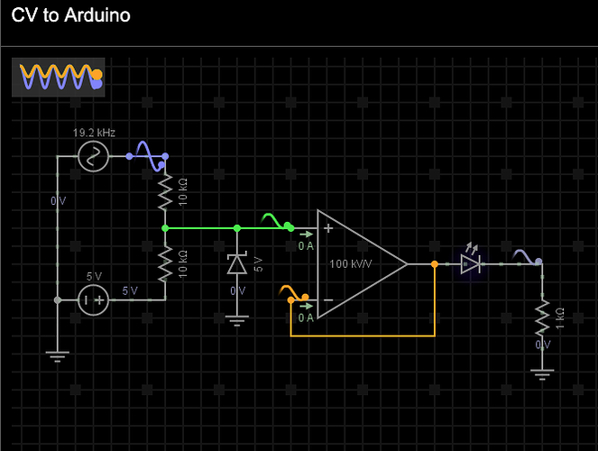
And my own (as it happened) unnecessary post includes a link to a lovely circuit simulation of the CV->Axoloti circuit route. Requires signup but its awesome, you even get to see the electrons flowing around it.
But I’ve run this simulation and added a voltmeter at the outpu and the output is 5v so it’s not quite as advertised. Some adjustment is needed.
I can't read schematics  that's why Im thinking the vactrol solution would be easier for me. But thanks for your answer. That looks complicated to me but it probably isn't. So you have tried that abd it works?
No I haven't but once I have time to stop researching and start playing I probably will 
I guess this was relevant, and you interacted on this thread. I surmised from it that optocouplers were only handling gates from this.
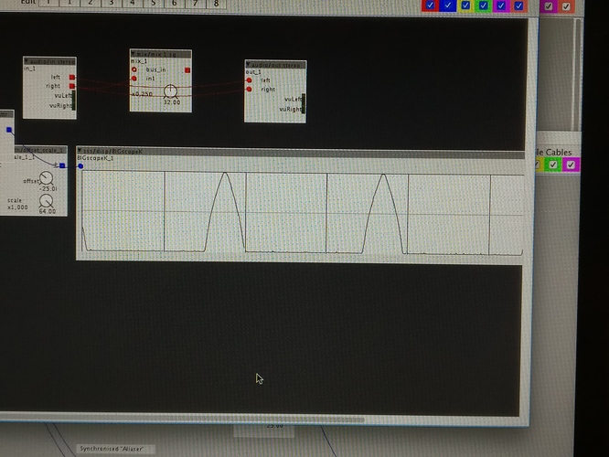
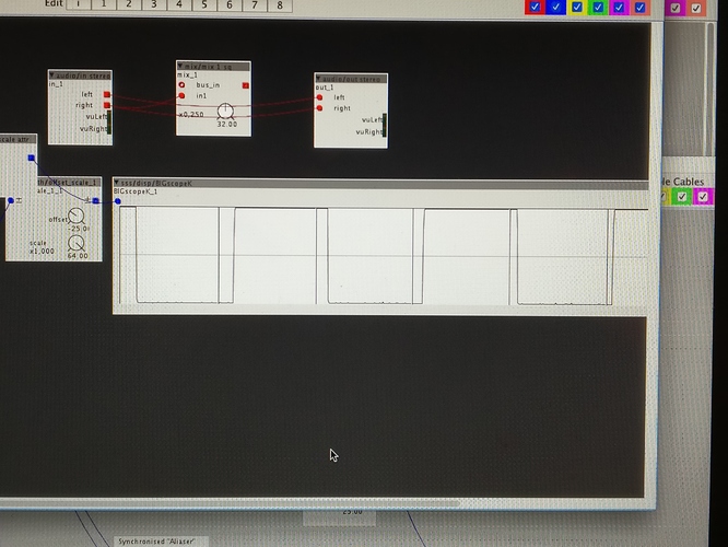
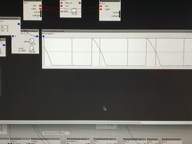
Now im testing the diy vactrol cv input. First feelings are impressed. I see from the scope that its accurate enough to draw the waveform to the scope.
Its only 220ohm . I tried with 10k but didnt ger any signal.
Edit:
Now i tried again with 10k and it works. I guess i had some wrong wiring first. I wonder if i did some damage with too small resistor
There is a nice kit (you can also order only the tiny pcb) by Synthrotek called VacPac that allows you to adjust the behaviour of the Vactrol. I use them a lot for CV to resistance tasks.
Cool, i wonder if i could adjust the scale with diy methods. I guess it's a different tjing to adjust the scale via axoloti patch objects versus adjust it by components 


