I know there are bits & pieces on this topic all over this forum, but I still got some questions.
+ I wanted to bring several solutions together in one thread.
(Even if I appear writing with seeming certainty, imagine a question mark after each sentence & let me know if I got something wrong. Thanks.)
Gates/Triggz - from & to Axoloti
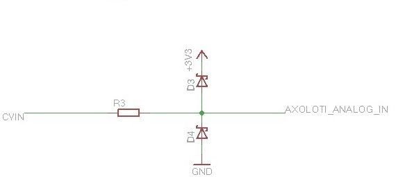
To interface Eurorack-Gates/Triggz with Axoloti directly you need to regulate the voltage of Eurorack down to 3.3v. You can use something like this & it is bi-directional:
- but what about 10v signals + do you really need exact 5v to 3.3v conversion to get the digital data? Just basic attenuation would also be enough - so basically a resistor? One could probably put a resistor between Eurorack-Gate & choose a value that even 10v gets attenuated to below 3.3v. I am a DIY n00b - so dear veterans, let me know if I talk BS. I think this is viable as we don't need exactly 3.3v. Just a simple change between any states can be digital aka "trigger-information", right?
& from Axoloti to Eurorack you'd have 3.3v - so just go directly. Most modules with trigger-ins just need a "raising edge" above a very low level. Sometimes as low as 0.x v. So 3.3v would function perfectly well directly.
For a indirect route there is this module specifically for Triggers to MIDI:
Data - Modulation from & to Axoloti
Eurorack to Axoloti
The direct solution from Eurorack to Axoloti here again would be to use the ANALOG capable INs, see here: https://sebiik.github.io/community.axoloti.com.backup/t/official-pin-outs-revised-work-in-progress/1284 - I counted 15 of them. BUT, here again you can't go above 3.3v or you would damage the Axoloti! So, the same idea, a resistor value that scales even 10v to below 3.3v to be secure, but here we deal with continuous information, so I am not sure how our data would be skewed through this theoretical resistor?! Is it simply scaled down? That would be good enough for me. I don't expect "automatic 1v/oct translation"  . & what about negative values like -10v? Not sure what a resistor would do here.
The indirect solution would be CV to MIDI (--> to Axoloti).
There are several modules out there, that do it:
(222 - this one does even notes, so 1v/oct to midi-note conversion, if you have a post-quantizer-note-stream from your modular you want to use inside Axoloti)
(delptronics not out yet)
There are even more modules.
Axoloti to Eurorack
It seems that PA4 & PA5 are the only analog OUTs. Do they put out also 3.3v? I guess so. So one could go directly to Eurorack with those two. There you could scale them as you wish. You won't get 1v/oct out of Axoloti though, unless there is some Axoloti-module which does the scaling? 3.3v would maybe be high enough in the note-range? Not sure if it is theoretically possible.
There are also Midi to CV solutions. Even more than CV to MIDI. Here are my 2 favorites:
Factotum does even back & forth, kind of: You can clock Axoloti from your Eurorack, while at the same time putting CCs & Notes & Gates from Axoloti out to Eurorack. But it does NOT CV to Midi (clock only). I didn't tested it yet, as I don't have this module. This should work in theory. Maybe somebody over here does this already?
Another great module, which is not out yet:
It has a couple of cool additional features implemented.
Another solution outside of the Eurorack-Format is:
Does also Midi-Note to 1v/oct & has a good price.
I have already ES3 & ES6+7 from Expert Sleepers, but unfortunately Axoloti has no Light-Pipe-I/O - otherwise I wouldn't even write this thread...
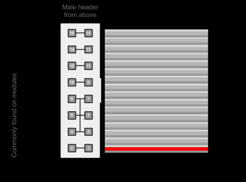
POWER from Eurorack to Axoloti
https://www.thonk.co.uk/shop/transient-breadboard-kit/
Questions
My basic question is: should one go the direct route where it is possible, because MIDI deals always with additional jitter & latency & 128-quantization, losing details? Maybe somebody tested out any Axoloti-MIDI to CV-Trig out solution & can say something if the beat is tight?
I am biased because I read the detailed MIDI-Jitter-Problem-Essays on https://innerclocksystems.com/.
They also have a module:
Though I am not sure in which category to put it. It needs a specific VST!
Here is a thread on this: https://sebiik.github.io/community.axoloti.com.backup/t/creating-a-similar-solution-to-usamo-with-axoloti/1085/2
To solve all this, some kind of Frankenstein-Solution comes to mind.
MIDI to CV (Module) would be more important, because the Axoloti got much more ANALOG INs than OUTs, but then again there are many uncertainties stated in this thread on how to make use of the ANALOG-INs, so going the full MIDI-Route?
In my particular situation I'd like to trigger/clock Axoloti from Modular then generate Triggers/Gates in Axoloti based on that Clock (divide & multiply e.g.) & put them out back into Modular, but I am not sure if this would be a mess through the MIDI-Jitter-Latency situation. How can I find this out? Dropping a few hundred €€ on modules to find out that it doesn't work properly? I have gone this route for the last 5 years in Eurorack  - I am pretty much burned-out already, but still don't want to give up.
OF COURSE there is the mighty, beautiful, amazing Euxoloti-Project ( http://build.irieelectronics.de/ ) - but Paul disappeared somewhere in 2016/2017 from the scene.  - He didn't respond to my mail.
Still, even the Euxoloti does not have any CV-OUT, only lots of CV-IN & 8 Gate-OUTs, which is cool enough in this compact Eurorack-Form-Factor. So additional Midi to CV Gadget would be valuable anyways. BTW, I wonder how there are 8 Knobs + 8 CV-INs - I see only 15 ANALOG INs.
Another basic question: I was confused that the official PINS can be Digital INS, Analog INS & Digital OUTS & PWM & more stuff I don't even understand. Can they be that at the same time? Probably not, where does the decision comes in? Are there specific Modules in the Axoloti Software to assign the PINS?
At the moment I am waiting for my first 2 Axoloti to arrive, so I can't try out much.
Maybe @Ersatzplanet @afghanblonde @paul can help/are interested in this thread?
I am using this type of web2.0 forum for the first time, damn it is great! So fluent & thought out & self-explained & interconnected. This is the future of forums.
THANKS. 


