Axoloti Core Board Failures


#1

A few unexpected board failures have been reported, here's the analysis.

Scope

  • Affects board revision 1.0, fixed in board revision 1.1

Symptoms:

  • The red LED keeps blinking forever after startup, while green LED is steady on
  • Establishing connection is still possible, but extremely low voltages are reported for the 5V supply and the VDD supply, and patches don't run.
  • IC3 (right behind the output jack) becomes extremely hot

(all three!)

Failure analysis:

While any short on the audio power supply would exhibit the same symptoms, the failures reported are caused by a failure of IC4 - that is the line output driver. Its failure causes the analog audio power supply (VDDA) to short to ground, and the regulator (IC3) heats up.
The damage to IC4 is permanent. The overheating of IC3 stops when IC4 is isolated from the power supply without damage to IC3 or other components.
IC4 fails when there is a large voltage difference between ground and line output ground. Normally this does not happen, many users have been (hot)plugging USB, in- and outputs countless times without failure.
The reason that line output ground is different from general ground is ground loop noise suppression. In short, IC4 acts as a little active DI-box, and the resistance between line output ground and general ground minimizes supply current to flow through the line output.
For details about the ground loop elimination circuit, refer to sloa143.pdf from Texas Instruments.

Causes

  • Some USB cables do not connect the shields between the two ends of the cable. This is in violation of the usb specifications, but not all cables comply with this...
    When plugging in such a cable, it is possible that VBUS (the USB power supply pin) connects before the ground pin.
    When there is a connection between line out and, for example, a soundcard, the PC ground is connected briefly to line out ground before there is a connection to USB ground.
    At that point the bypass capacitors across VBUS are still uncharged so the whole 5V from USB VBUS applies between line out ground and general ground, and kills IC4.
    A proper USB cable connects the shields of the two ends of the cable, and the shields connects the ground between PC and Axoloti common ground before the USB pins make contact, and no supply current will flow through the line out ground.

  • Using the DC socket power input with a non-isolated adapter.
    A DC barrel socket does not guarantee the order in which connection is established: ground first or supply first. When using a typical off-the-shelf adapter, there is no problem, as it is galvanically isolated from any other connection.
    When one power adapter with multiple DC plugs is used with interconnected equipment

Adding protection to the line output

The voltage between line out ground and common ground can be clamped by adding two diodes:


The suggested type is 1N4001, 1N4004 or 1N4007, but most rectifier diodes will be fine.
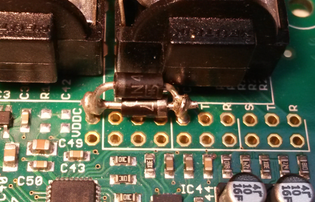
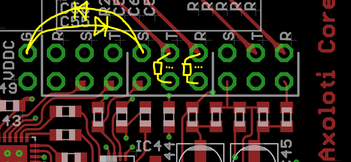
While you're there I also suggest to add output resistors. This eliminates distortion caused by overloading the line output driver when a mono jack cable is inserted in the line output:

Recommended resistance is 20 to 100 Ohm. Cut the tracks on the bottom side of the board where the yellow triple dots are.

Board revision v1.1 ("Axoloti Core v1.1" is printed on the edge of the circuit board) has these diodes and output resistors already.


Strange bug with flashing red led and low voltage report
Axoloti Core Doesn't turn on anymore (Officially deceased)
Control transfer failed: -7 - need a little bit of help
I think I fried something
Control transfer failed: -7 - need a little bit of help
#2

Is the new batch of boards all of the 1.1 variety ?


#3

Shipping board revision 1.1 since December 3th, 2015.


#4

thanks for the fix suggestions. will implement to be safe.


#5

Perhaps this post should be pinned ?


#6

#7

Great to see a full breakdown of the problem, and solution.

a few questions for clarification:
- for the USB cables, we should check there is continuity on the outer shield, then we should be ok? (assuming we dont use the DC supply)
- do the proto boards not have this issue, as theu dont have the groud loop suppression (and so I assume IC4) ?
- is the USB still an issue, if you are not connecting the audio output directly to the PC... e.g. if your going via a mixer?

Im tempted to get the parts and do the prevention fix, but I wonder if its truly necessary... though the mono plug fix could be useful anyway.


#8

Continuity between the plug shields on both ends of the USB cable is what matters.
Using a DC supply is fine, if you use it with an off-the-shelf wall-wart powering only Axoloti. Not if you use some sort of DC split cable to power a mixer and axoloti from one power brick or battery.

v0.5 prototypes did not have the ground loop suppression circuitry, so unaffected indeed.

Your mixer connects audio ground to soundcard ground to pc ground. Only a bit more indirect, but the same issue applies.


#9

I have a 1.1 board but I am still getting some pretty bad audio failure if my signal gets to hot. I am using a mono out audio cable, and have the board connected to the computer via USB and powered by a DC wall wart. Like "stuck with a crackling sine wave until I unplug everything" bad. At first I thought it was a patch I was working on, but as of this morning it does it with all patches I load on to the board.

Is using mono cables just out for these fellas?


#10

After troubleshooting in private communication:
@fma's issue is resolved and not a board failure.


#11

Johannes was massive help BTW! Public thank you Johannes.


#12

Noob question: would 1N4148 diodes also do the job? thanks


#13

Untested, but I expect that to be fine.


#14

cheers Johannes, I was getting concerned in my googling "the 1N4148 is a typical signal diode and can only handle 200mA, while a rectifier diode like the 1N400x will work for 1A" but wasn't sure what sort of current would be between the two points. thanks for the help.


#15

Yes, the 1N400x can handle more current, and has my recommendation. Normally there is only little current going through there, it is unexpected currents that have caused some failures. I think in practice 1N4148 is fine.


#16

Hello, I have a V1.2 board with the same problem, IC3 is just warm, but cooler than U2 and the ARM processor, I can't find a fix in this thread, is there a fix?
My board was working fine yesterday, and the USB cable shields are connected.


#17

PM sent.............


#19

Hi! Same issue and description made by DiegoLiedo in a V1.2 Board. Any suggestions? Thanks in advance!


#20

This issue is an abomination. Boards should never have been shipped like this. I bricked my first Axoloti, no idea how - just dead and red flash of doom/low voltage.
Went through the trouble to buy a new one 2 weeks ago (both rev 1) - installed the mentioned diodes. And after doing that (with pro soldering gear) the unit is DEAD. Fuck me, thats unbelivable - unbelivable to ship out a product like this.
I will strongly recommend anyone to never buy a rev 1. It's way to fragile to use in any sort of setting. :frowning:


#21

Is there any chance of reviving boards when they're fried?
I've now got 3 boards that got fried (one v1 and one v1.2, the other I can't see atm as it's in a case), all showing a very low voltage (though there are differences: the v1 shows around 0.2v and the v1.2 shows around 0.4v for the 5v.

Would be nice if we could find a fix for these failed boards (at least knowing which parts you might need to replace and which parts shouldn't cause the problem).