Axoloti as a 5U Module


#1

Hi all:
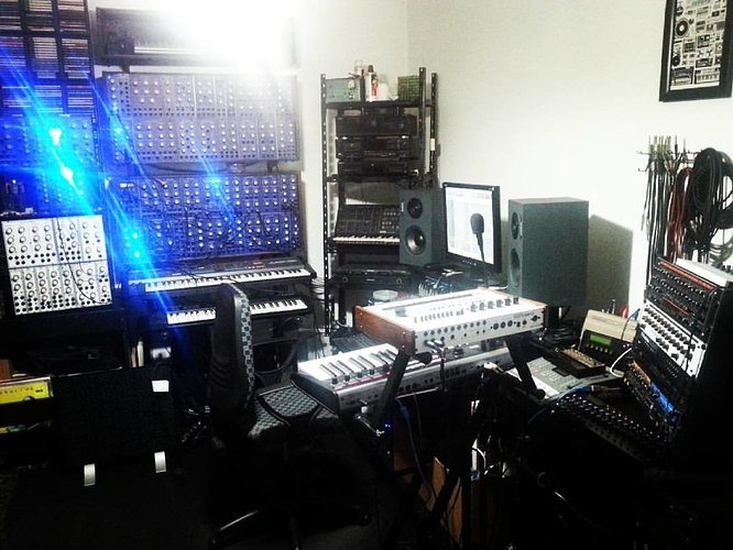
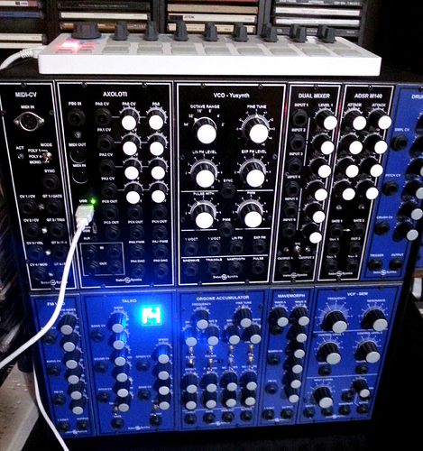
I did a module with Axoloti for my 5U modular.
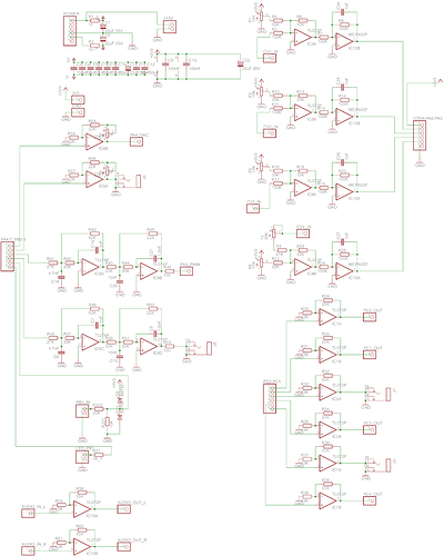
The module have:

4 CV inputs (CV control + CV Atenautor) connected to PA0 to PA3.
1 Digital Input (with voltaje protection) connected to PB0.
2 CV outputs (0 to 10V) connected to PA4 and PA5 DAC outputs.
2 CV outputs (0 to 10V) connected to PA6 and PA7 using PWM at 10KHz.
6 Digital outputs connected to PC0 to PC5.
1 LED connected to PB1.


Notes:
I used MCP6002 (not MCP602), just didn't have a library for the MCP6002 in Eagle. And they are powered with 3.3v and GND, the rest of the opamps are powered with +15v and -15v.
The filters for the PWM outputs are Bessel 4th order with a frequency cuttoff of 1KHz. I modified the pwmt3 objet to have a PWM frequency of 10KHz to have very good filtering of the carrier, but works well with a PWM frequency as low as 3KHz.

CV in to Axo analog in (gpio)
Trying to make CV-in / CV-out addon for Axo
Is is possible to have analog outputs (+/-5V)?
Connecting Eurorack VCO to Axoloti line in
Increasing the 3khz control rate frequency
#2

I see that this Axoloti have some nice neighbours !


#3

All DIY :slight_smile: and some of my own design :astonished:


#4

Great stuff, I see you built a YuSynth VCO.
I think it is really worth it to make analog modules when it comes to modules that cause aliasing in the digital realm, such as distortions and radical wavefolders/processors.


#5

I built a lot of analog stuff (here is a picture of my actual setup, about 60 modules all DIY), I just started to build digital stuff about a year ago, first did some Arduino modules, then some Teensy and finally I did a module with the Axoloti.
I didn't care much about aliasing because I think it gives some character to the sound as in old digital synths... And when I don't want aliasing I have real analog stuff... There is a few times when I want to do complex polyphonic analog pads that I can't make with my modular (or any of my other synths) when I try to avoid aliasing...
Apart from that is a lot of fun to patch the Axoloti with other modules, using analog filters, processors and control modules...


#6

how did you modify the pwm output to 10khz? did you just change the 4096 to 400?


#7

The exact frequency is 10253.90 Hz.
I modified the line like this:

  <code.init><![CDATA[static const PWMConfig pwmcfg = {42000000, /* 14MHz PWM clock frequency.  */
4096, /* PWM period is 4096 cycles.    */

I can't remember the exact math at the moment, I have to check my notes.

Also, here is the object:
pwm t3 Sebo CV3.axo (1.7 KB)


#8

ah ok, so to change it to an 8bit output at 32khz i would have to do something like: 8192000 and 256? that would be great if that would work!


#9

If you mean for audio playback, isn't so easy.
I tried with a PWM frequency of 41KHz and 8 bits (256 steps) but the object expects a krate signal, I tried to convert one input of the object to srate, but I should be doing something wrong because I got a lot of aliasing, like if the object still working at krate.
My coding skills are VERY limited, so probably I'm doing something wrong...
If you get it to work, please share the object...


#10

For 41KHz I've used 10500000 and 256.

And just to clarify, the PWM output works well at 41KHz (I checked with my oscilloscope) the problem is getting the audio to the object.


#11

ok, i will try and see what it sounds like :slight_smile: i will of course share if it works out ok...


#12

Out of curiosity, did you do this on perf or get a board printed? I'm always keen to see people's layouts.


#13

I've etched the PCB myself...
But I did some mistakes in the original design, so I had to correct them cutting some traces and adding some flying wires, that's why I'm not sharing the PCB layout.
I've corrected the schematic (the one I shared is corrected), but dind't have the time to correct the PCB layout...


#14

Fair enough. :slight_smile:

I'm working on a Eurorack perfboard layout for a very similar setup, challenging since I want to fit it in sparse skiff space. Might just bite the bullet and have it manufactured, no room here for etching or milling a board.


#15

Yes, Euro is too small, you have to go for SMD to get a small module.
Mine is all tru hole and the PCB is big (something like 200mm x 75mm).
I could share the .sch file if that makes your work easier, but as I said is all tru hole.


#16

Thanks, but I have what I think are pretty robust schematics for mine, it's just board layout that's challenging. For certain I would go SMD for most components if I were to get a board or two printed, prefer that way of working already, or should I say debugging.


#17

hmm, i'm getting also heavy aliased results. i scaled and offset the audio to be only positive, but a sine above 600hz still sounds rubbish :frowning:
@johannes, can we make the pwm out's cheap audio outputs? how would one write at audio rate to the pwm pin?

this would be just so cool for dirty 8-bit stuff, and you would not even use up an audio out.


#18

i found this entry on GitHub, it is a little confusing (i guess the comments were not changed to reflect the actual numbers...

// generate 8MHz clock on MCK pin with PWM...

static const PWMConfig pwmcfg = {168000000, /* 400kHz PWM clock frequency. */
21, /* PWM period is 128 cycles. */
NULL, { {PWM_OUTPUT_ACTIVE_HIGH, NULL}, {
PWM_OUTPUT_ACTIVE_HIGH, NULL},
{PWM_OUTPUT_ACTIVE_HIGH, NULL}, {
PWM_OUTPUT_ACTIVE_HIGH, NULL}},
/* HW dependent part.*/
0,
0};

but there is an additional zero at the end, hmm...


#19

I think that isn't the problem... As I said, the PWM is working well, I can measure the 41KHz a the GPIO output, the problem is how the object handles the audio, and how modulates the PWM signal...
My guess is the object is coded to work at krate, so even I converted one of the inputs to srate the audio is still prcessed at krate... But I don't know how to change that...


#20

here is what i tried. (i changed the bit shifts as well, to accommodate for 8bits instead of 12 and the greater range of s-rate signals)

pwmtry.axp (3.7 KB)