Increasing the 3khz control rate frequency


#13

Alright, thank you for that! So I could somehow think about using a 16 x 16bit buffer/shift register which is clocked out with the samplerate and loaded on each k-rate.
Perhaps K-rate is also enough. I just recognized that it is a bigger problem that my midi controller "akai midimix" cannot send NRPN cc messages. I mean that i can only get 0-127 steps from the faders which is not perfect. But it might be also okay when i use a smooth object in between the midi values and the "DAC object" input.

Anyways, if 3000Hz is not enough, is it possible to setup an extra timer + interrupt routine which is running faster?

#14

Wow thanks @ricard for the thorough explanation i finally understood a lot of issues i was running into recently. You should copy this into a user guide thread...


#15

@Flub - what is the maximum frequency you want to send using these DACs?


#16

I am not sure yet. I want to make possible as much as possible so actually 48khz would be awesome to have. But I would just be fine with 3000 for a beginning.

I ve got a quick question about dynamically reading the inlet values.

disp_d1 = inlet_i1 >> 11; 
//setDAC(1, X, (inlet_i2 >> 11));
for (uint8_t i = 0; i < 40; i++) {
   setDAC(i, X, inlet_i??? >> 11));	
}
pulseLDAC();

I think you see what the problem is. Do you know how it is done to dynamically compose those constant names ?


#17

You could just put the inlets into an array, like this:

int a[3]={inlet_i1,inlet_i2,inlet_i3};

And then use a variable to select which slot of the array you want to select:

outlet_l = a[param_sel];

Another way is to take advantage of srate inlets. If you are using many inlets, this is going to be the easiest way I think. If you are routing tons of cables, using this method can make bi patches a little bit easier to comprehed and work with.

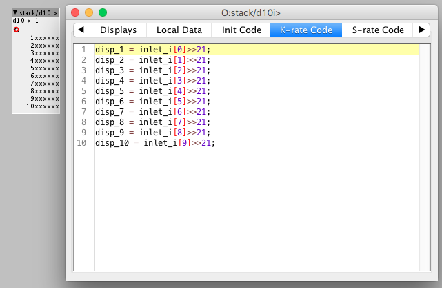
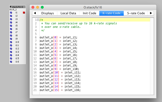
If you make srate inlets, the red ones, but put the code into krate fan, you can actually route 16 krate signals through a srate inlet. Krate is 3000 srate is 48000, so 48000/3000=16.....

Something like this image below. Here I have ONE single srate inlet and then I use inlet[0], inlet[1], inlet[2], etc. to display each value from each of the parts of the inlets.

You can simply use:

inlet_i[set number here]

to select one of the 16 inlet_i[x]


#18

Cool thank you! I just wanted to test it out, but i could not connect more than one blue line to the red input. How is that possible?
Anyways i think I will take that array approach so i can also check if the value changed before sending it to the DAC to save performance. When I send all of them it takes 60% of the cpu.


#19

See here how you get the values in. If you don't need many inlets, this is probably not the best solution. But if you do it's a lot easier.


#20

Ah now I get it. Thats a nice trick and good to know : )
I think I am gonna do it with a table and a kind of helper object where you can select the table index you want to control. so I can put the inlets for the DAC outputs speperated anywhere in the patch.

Another question:
I now implement the code in a patch/object. Is it somehow more perfomant to export it as a real object somehow? I dont know how to do it, but I am curious if it is worth trying out.


#21

If you want to make an object instead of a subpatch I think there is something to gain. All the inlets uses ram. So ilets sat you have 10 objects inside a subpatch and they are all connected via in/outlets and you code the 10 objects in one single object, you don't have all those inlets/outlets anymore and you can save the memory used in the subpatch.


#22

Here is a the working AD5370 Patch:eval_board-control_dev_18_40_squares_test.axp (53.5 KB)

I did not use a subpatch i think. But i used this "patch/object" object to put my code for the DAC somewhere. I dont know if that will benefit from being an object like the ones which i can select from the objects list when i double click.
__ EDIT __
I just found out that the file menu of the object editor offers the option "copy to library" I did it and it did not change the performance.

So actually the main question is actually. Is there any way to output data faster than 3khz .


#23

If you build the lfo into the object, you have saved 80 inlet/outlets. I think that's worth considering.


#24

And yeah if you make it into a an object and save it to the library, its easier, cause you dont have to copy all the object over and over again every time you made a change in one of them. You just save the object and all of them will be changed right away.


#25

@jaffasplaffa They are just there to test the performance of different amounts of DAC Channels to be updated in a k-cycle.
The Data is only sent when it changed.
Cool, thats what I did not know. Then there is actually no reason to use the patch/object for me anymore. I thought it is not editable anymore then.


#26

The limit you're hitting isn't caused by the 3khz K-rate. You're being limited by the actual speed of the SPI link. Observe the DSP load %, running with FPCLK/4, FPCLK/8, FPCLK/16. And the square LFOs are probably reducing the number of SPI writes.
Note also - the SPI writes are synchronous, nothing else gets done while bits are in motion on the SPI.


#27

As you've noted there shouldn't be a difference in performance, it all ends up in one big function when the patch is compiled anyway.

I find patcher objects handy when developing objects as it means both the object and the surrounding patch are saved together and it's not necessary to keep the files for the patch and separate object that you are working on in sync.


#28

This is the working patch now:
basic_setting.axp (8.5 KB)
For anyone who wants to use that 40Ch 16 bit DAC Board too: It only worked reliably on Clockarte FPCLK/4 when i put 10 Ohm termination resistors on the axoloti boards CLK and MOSI.

It is just working fine except two problems.
The first problem is actually the reason why i started this thread. The control rate of 3khz is not ideal for smooth sweeps. A sine Lfo cannot be used in higher Frequencies as it is a strange staircase then.
The second problem is that the patcher or actually my hole OS freezes when constantly turn the dial around for 20 seconds in the patch "basic_setting.axp". My mouse is not visible anymore and nothing interacts. So I have to reboot.
Has anyone an idea what the reason for this is? I am using windows 10 at the moment and the axoloti patchers version is:
Build Version: 1.0.12-2-0-g60a2f99
Build Date: 08/04/2018 20:20:07 CEST
Java version: 1.8.0_161

I could not find a log file which is telling me what happened thats why I am kind of clueless...
- Flub

--- EDIT
The problem only occurs when i have multiple DAC output objects at the same time.

attr_table.array[attr_channel] = inlet_i1 >> 11;

I think somehow it is problematic to write to multiple keys of the array from many "patcher/object" objects at the same time... Is that possible?

in my DAC controller object i call this at k-rate:

for (uint8_t i = 0; i < 40; i++) {
	if (attr_table.array[i] != DACLevels[i]) {
		setDAC(i, X, attr_table.array[i]);
		DACLevels[i] = attr_table.array[i];
	}
}
pulseLDAC();`

__EDIT:
I just realized it is not freezing anymore when i set FPCLK/8 instead of FPCLK/4. Can it be that there is somekind of problem with the SPI library?


#29

Hey there, very interesting project! Could you get it to work properly in the end?

I was wondering: could this be used to achieve very lo fi extra audio out (with everything cut above 3k)


#30

Short answer: NO.

There is another thread were Johannes explain how to do it but is very complicated, I think nobody tried...
I modified the code to get good CV control out of the PWM outs, but not audio (well I mange to get audio, but it sounded horrible).


#31

ok thanks. I would really love to have one more mono out to use as an fx send...

Are you using that adc in the end or do you use the pwm pins directly for cv control?


#32

I think you mean if I'm using the DACs or the PWM outs to output CV. I'm using both (and also I'm using the ADCs to input CV).
I'm using the 2 DACs plus 2 PWM outs, and I regret not having used more PWM outs, as they work very well.
Here, I let you a link to a post with what I did: