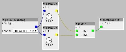
I'm wiring a bunch of pots to my core, and to simplify wiring, I want to solder a wire into one VDDA and one GND and then split that into 5 parallel wires to go to the pots. But of course, this will increase the current drawn by up to 5x. Is this a worry for the core?
Wiring potentiometers in parallel. Should I worry about overdrawing current?
i don't understand. i think there is no other way to wire it, or is there? make sure you use an individual analog in for every pot 
I usually mount a protoboard with headers onto the Axoloti instead of soldering it directly. I've used one VDDA for 14 potentiometers in the past and it works fine.
I just wanted to be sure. I don't want to fry my little computer! And of course I'm doing the inputs like that!
Currently wiring 3-pos switches in parallel as well and having some trouble because of bleeding into each other...
The wiring is as such for every switch (they are 3) :
leg 1 : VDD
leg 2 : to analog in
leg 3 : VDD/2
Then I read them like this : 
... to have a 0 / 1 / 2 position (well, actually 1 / 0 / 2 but it's fine). Maybe the voltage divider is a strange method but it was working... At least, for 1 switch.
Unfortunately if I'm moving the first one on the chain, it changes the values from the other switches....
Am I missing something ?
Exactly what kind of switch are you using? Typical 3-position switch is 'SPDT, center OFF'. Are you using resistors to create a voltage divider?
If they are the same kind of switches I have, leg 2 will not be connected to anything while the switch is in the middle position. That means the analog input is open, and in the hardware world (as opposed to the Axoloti patcher) an open input does not automatically become zero. Instead it is "floating" or undefined. Typically an open analog input reads the same voltage as the pin next to it, or any random voltage from static electricity on the wire or even the signal of the nearest AM radio transmitter.
So you should make sure that the analog input is never totally unconnected. In this case, a pull-down resistor would help, i.e. a resistor between the analog input and ground. Of course that resistor would then in turn influence your VDD/2 (when the switch is in that position), so it needs to be relatively high.
A better solution: connect leg 1 to VDD, leg 2 to analog in and leg 3 to GND, then add one resistor between leg 1 and 2 and another resistor between leg 2 and 3. That way the analog input is always connected to a well-defined voltage and each switch has its own voltage divider, so they don't influence each other. As to the resistance value, I would use 10 kOhms (because I have those lying around already), but anything between 1kOhm and 100kOhm should work. Lower resistance values draw more power, higher ones give a slightly unstable signal.
Resistors aren't really needed. Yes, a floating input isn't precisely defined, but it won't be 0 and it won't be VDD. So Connecting leg 1 to VDD, leg 2 to analog in, and leg 3 to ground, you can test for very low (grounded side), very high (VDD side), and anything else is middle position.
Maybe use one resistor between leg 2 and analog in, just to ensure low current when switch is in VDD position.
