Using the unused Midi Pins


#1

I use two Axoloti Boards, on being feed in as a send return insert for the other. Information is being passed between the 2 boards via midi.

Since setting up the audio send/return is quite annoying with stereo breakout cables I thought about using the 2 unused pins of the midi connector for the audio connection.
I see that these have solderpoints on the boards. Could I just use these? Theoretically this should be M1 and m3 right?

Next question is: If I solder from the audio in and out pins above the Gpios can I still use the Stereo Jack I O?

#2

I'm not sure all (premade) midi cables actually have 5 wires inside. Pins 1 and 3 of the DIN sockets are indeed unused, and wired to solder pads MI1, MI3 (input socket) and MO1, MO3 (output socket).
The solder pads carrying audio (labeled LIN+, LIN-, RIN+, RIN-, LOUT+, LOUT-, ROUT+, ROUT- ) are biased at 1.65V, do not use those as line in/out without coupling capacitor. The solder pads behind the audio jacks are the ones to use in this situation.
There is an important catch: if you insert a mono jack into the stereo jack input or output socket, this connects the right (input/output) channel to ground via the jack sleeve, so even if you tap the signal on a solder pad, it will be muted when you insert a mono jack. This can be solved by disconnecting the right signal from the jack socket, but then the jack sockets will be left/mono only. I don't see an easy golden solution...


#3

Ok thx for the detailed answer.

You're right, most of them only use 3 wires inside. But you had these kind of connectors on old hi fi systems hey usually have 5 wires. But i would solder them myself anyway.

This is all good to know, since I was planning on using one IO from the solder points and one by inserting a mono jack.
But afterall I want to have only one external in and output. Meaning that both boards get the same Input (my guitar/other instruments) that is being split and in the end boath boards should be mixed. So I could just not use the onboard jacks and at one jack for In and one for out.

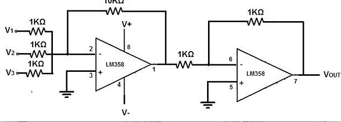
Any tips for a simple circuit that would sum the output of two boards?


#4

I was looking at something similar, but since my knowledge about DIYing is fairl limited, so I never got started on it. But I did do some research on making something that several Axoloti could be summed into.

Passive summing mixer:
Very simple, doesnt need power, but channels can easily bleed into each other. This is not really an option. I asked a bunch of questions about this type in a DIY group and everyone told me not to build it. So I forgot about it.

I was suggested an active summing mixer:
Needs power, but no bleed.

From this facebook group:
https://www.facebook.com/groups/synthdiy/permalink/10153665170911313/?comment_id=10153665567821313&notif_t=group_comment&notif_id=1462728997773585


Simple Summing Mixer
#5

Hey Jaffa,

thx for the schematics. I'm actually in the same FB group :wink:

I got a cheap conrad 4 channel mixer yesterday (active, needs 9v) so I will first use this, but in the future I definately want to build several axolotis into an enclosure, then it will come handy if I can make my own mixer circuit.

@johannes Considering the audio via the midi cables plan: Do I need to have an extra ground? There is one with the midi connection anyway, shouldn't that be sufficient?


#6

Do you have a link for it, might be interested in it too? Also do you think quality is good enough?


#7

Didn't try out the conrad yet,a friend of me gave it to me. I also have this behringer mini mixer:

It really sounds ok. I opened it up and it seems there is not much that could be extremly noisy like mic preamps or eqs.

But I'm also not extremly concerned with sound quality, as long as it does the job and is not extremly noisy. With these little mixers I have the feeling that there is not much that could go wrong as it's quite simple circuits.


#8

Yes, please use one wire to connect audio jack grounds, MIDI does not connect grounds.


#9

am I reading this correctly? audio over the midi-cables??
Are these seperate in/outputs which can be called upon within the code?
Would be nice if we'ld be able to use several different ways to send audio to connect mupltiple boards..


#10

hey! does this mean that if I remove the 5-pin DIN sockets and intend to use the MI1 to MI5 and MO1 to MO5 solderpoints, I can just ignore solderpoints 1 and 3 for both in and out?


#11

Yes you can ignore them!


#12

thanks!

then I shall remove the DIN connectors, the audio jacks and the USB for my axos to fit a smaller enclosure. shouldn't be that hard, right? I've watched plenty of desoldering tutorials...