Using a CD4017 as an external sequencer


#1

Hi, I have a load of CD4017BE chips not being used, and after thinking about it, I wondered if it was possible to use them as an external <11 step sequencer.
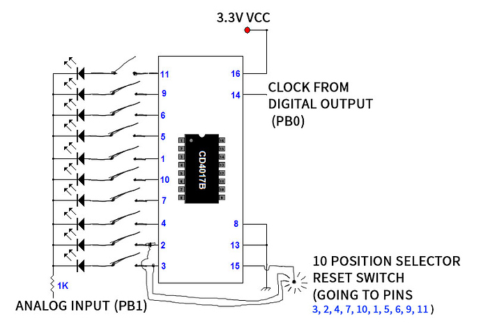
They seem to say that they can work from 3V-15V, so I imagined a very simple circuit like this :

The clock is sent by a square LFO, sent out on a digital GPIO.
The sequencer output would be sent to a GPIO input
If I use switches like on this example, I would have a 2nd LFO going twice the speed going into an AND to get each beat (even when it doesn't change)

The reset switch would be hard wired to a 10 position selector switch, so that I can have anything from 1 to 10 steps per sequence

I'm using LED's to get visual feedback from my sequence, and also I hope, protect the circuit.

Has anyone ever tried doing this kind of thing, or does anyone see anything that can go wrong ?


#2

That's a classic. Here's a link to Mark Verbos' OG article about that. You could also put potentiometers on each output to change the voltages. http://www.midiwall.com/gear/babyseq/


#3

Thanks, it was the Baby 10 Sequencer that gave me the idea, and after reading about LED's a little and looking at my circuit, I think I need to use any 1N400X diodes instead of the LED's and make a parallel circuit for the LED's (and not forgetting resistors either) going strait to the ground.
I might breadboard up a version tomorrow and see if my chip likes 3.3V and see if it accepts the clock from the axoloti too...


#4

The 4017 is the basis of tons of hardware sequencers. I have made many variations of them. The Oberheim Mini Sequencer is made with the brother of the 4017, the CD4022 which is a little more musically oriented with 8 steps out instead of 10. Here is a link to the Oberheim Mini Sequencer if you want to check it out. There is a lot of extra circuitry (quantizer and built in clock) that is easy to remove but the core is easy to follow.


#5

I have thought of this idea as well, however my main concern was that for my needs, what would happen if a trigger fails end it ends up out of sequence, or how do you prevent this from happening. Not only that, you can't position to an actual step without stepping through the previous counts. For this reason, I decided if and when I do, I will just use a micro controller which could easily be controlled and also add control over midi.
:grin:


#6

I have thought about that problem, and I planned about putting a push switch on the reset pin, so that I can re-sync the first step. I suppose you could do the same with the clock input, and advance each step manually.
But like you, for the moment, I'm using midi controllers and doing all the sequencing in the patch. I just thought it would be a fun way to save up on inputs while using a sequencer.


#7

What you want then is a CD4028BM or CD4028BC which are BCD to Decimal Decoders. They have 4 digital ins and 10 digital outs. You present the BCD coded digital number on the four inputs and that chosen output goes high. This way you can jump to the step you want high directly in any order you want. Basically it is the CD4017 without the internal decoder. You could easily drive it from the Axo digital lines if you drove them with a Binary Coded Decimal code.


#8

I'm already doing that between the Axo and Arduino due.
5 out of the Axo as binary integers into the arduino, read 0 to 31, 0 to 15 for the first seq, 16 to 31 for the second. Just pickup the change in range, works perfectly. No need to stress with IC's.
:grin: