I noticed that there are unipolar2bipolar, and bipolar2unipolar conversion objects (axos). What are they for? When do they have to be used?
Unipolar and Bipolar: What does it mean?
When you see inlet with + sign it means this inlet is intended to use unipolar signals so if you want to connect LFO outlet with +/- signal to it you need to convert it. You can skip it then this unipolar inlet will read only positive part of your LFO signal.
I saw the code chunks in bipolar2unipolar.axo and unipolar2bipolar.axo. I think I understand.
- a unipolar is an unsigned 8.24 fixed-point value, that is, 8 integer and 24 fractional bits (range 0.0 .. 255.99x).
- a bipolar is a signed 7.25 fixed-point value, that is, 7 integer and 25 fractional bits (range -64.99xx .. +63.99x).
- unipolar2bipolar/bipolar2unipolar maps between the two.
Am I correct so far?
Is this documented somewhere?
I think that's not quite what happens. The conversion maps values between signed and unsigned, it doesn't change the phase of a wave. The code operates on sample/control values, there's no waves involved.
Can someone please confirm or explain the fixed-point format in use here? How wrong is my understanding? Trying to wrap my head around it, it's been a while since I did fixed-point math.
Try it yourself. Take for example lfo/saw r... which has got a unipolar output.. and connect it to a unitobipolar and connect that to a scope...... and you will see the phase change.
Also try with an oscillator. It does change the phase here too.
Sorry I cant help with the math issue.
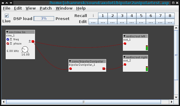
Ah. I had to try that. So I made a little patch to test it. It has an osc/sine which outputs to the left channel. A copy is sent throuch bipolar2unipolar to the right channel.

My first Axoloti patch ever! 
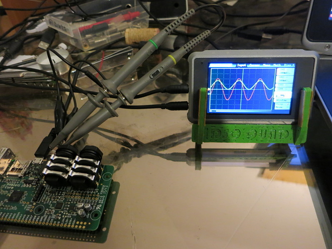
Then I hooked it up to my pocket scope:
Sorry for the bad photo, but you should be able to see that
- the red channel is centered about 0V and has a large peak-to-peak range. This is the left, unconverted channel.
- the converted channel shows only positive values and has about half the range.
- there is no phase change. There can't be, because the conversion code operates on single samples at a time. What you're probably seeing with 2 separately triggered software scopes is that they both trigger on the zero crossing, making it look like a phase change.
So apparently the bipolar ranges from -1 to +1 in terms of DAC output voltages (minimum/maximum voltage), and the unipolar ranges from 0 to +1. In terms of bits, a unipolar is an unsigned 7.25 fixed-point, and the bipolar is an 8.24 signed fixed point (kind of the other way than I originally thought). It is starting to make sense to me now.
Correct me if I still got it wrong. I'm tired.
Well, it changes the signal from being a bipolar to a unipolar. The phase of the sine osc changes from bipolar to unipolar.
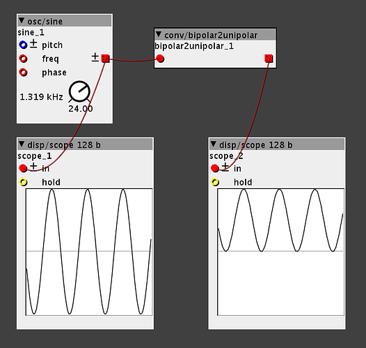
Look at the picture I posted of unipolar and biploar and look at the picture you posted. They are almost identical, except you used sine waves, and I posted triangles.
Sorry, they're not the same. There is no phase change. I explained why it would look like a phase change on 2 separate (software) scopes with separate triggers.
So if the bipolartounipolar object doesnt change the signal, the phase from bipolar to unipolar...
Then tell me what it does?
unipolar = 1 pole
bipolar = 2 pole
Unipolar signal stays ABOVE the line and is therefor only using one pole. The + pole.
Bipolar signal goes above the line as well as below the line. Therefor uses 2 poles. Both + & - pole.
Something happens to the phase. Call it what you want, but something changes.
Just a confusion of terms here, I think. Phase is related to time ("X-Axis"), not amplitude ("Y-Axis"). The signedness and offset of the signal is changed by those axo objects, not the phase. That much I understand now.
I didn't want to sound patronizing or anything - I asked a question, and then I just wanted to note down the process of my old maggot-ridden brain slowly understanding this, in case anybody else wonders the same thing. Or in case someone comes around and tells me I counted the bits wrong... Which is possible...
(post withdrawn by author, will be automatically deleted in 24 hours unless flagged)
No need to use an external scope, although it can be handy if you want to show two signals at the same time. Axoloti has some dedicated objects to display signals. You can find them in the disp folder in the object selector.
Right, thanks. Problem is, I wasn't sure if the two separate scope displays are triggered/refreshed at the same time. A two-channel scope is an easy way to check whether the signals have the same phase.
I know. That's why I added it to the wishlist of objects: https://sebiik.github.io/community.axoloti.com.backup/t/wishlist-of-objects/489/72


