Just got my Axoloti and I have a couple of simple hardware questions:
1. What is the maximum allowed peak to peak voltage at the audio input jack(s)? I'm not concerned about input distortion but I just don't want to damage the board. I understand that the gpio has a 3.6vdc limit but the max audio input levels are not specified.
2. What is the largest size of external sdram card that can be used by the board? I also understand that the card must be FAT formatted but that really doesn't define the max size.
Two simple, newbie questions
- neg - 1.65 to pos + 1.65, the GPIO's work of a standard of 3.3V.
- Not entirely sure the max, but https://sebiik.github.io/community.axoloti.com.backup/t/sdcard-benchmarks/436 is a topic goes through a variety of card sizes and also covers performance benchmarks of the cards that may be of some use to you.
Thanks, you're right about the 3.3v on the gpio, my typo. But the audio out can swing a lot higher than +-1.65vdc. It surprises me that the design would be so lopsided. I also have a large modular synth and it can generate at least +-10vdc signals which I would like to use with the Axo... I just don't want to fry the board.
According to the datasheet for the audio chip, full scale input voltage is 2.83 V peak to peak. so voltages higher than that will clip and possibly damage the input to the main audio chip if it's driven too hard for too long.
Gavin seems to think the maximum voltage is 3.3v peak to peak, I'd like to know where he got that figure from, that datasheet for the chip says 2.83.
You could test it with a signal generator and a scope I guess, gradually increase the input voltage until you start to see clipping on the input.
Thanks again Gavin and strum! I have scopes, signal gens, freq counter, meters, etc. and can run the tests needed to design interfaces to the board. I was just hoping there was a better spec sheet for this board. However, from what I've seen of this forum, there is a wealth of answers and solutions.
Have I miss interpreted this info..
"The solder pads carrying audio (labeled LIN+, LIN-, RIN+, RIN-, LOUT+, LOUT-, ROUT+, ROUT- ) are biased at 1.65V"
or am I getting it confused with head phones out ??
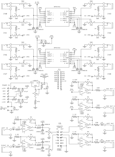
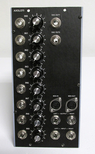
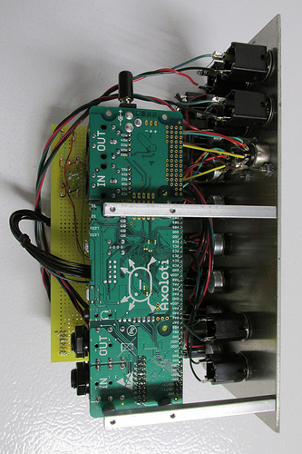
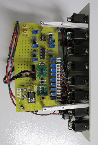
Some progress made. The audio in (at the stereo jack) will take -1.65v to +1.65v before clipping which is consistent with the gpio inputs of 0 to +3.3v. For the gpio inputs I found some low voltage, rail-to-rail opamps and am amazed how well they work... never used them before. They're powered directly off the Axo board's gnd and +3.3v so any excess signal into the opamps clip perfectly at 0 and +3.3v. The bipolar audio input was trickier so I just ran them into 'normal' opamps powered at +-15v and set the gain such that they clip just after my desired, useful levels. Then let a pot take the signal down to safely enter the Axo's inputs. The dual Schottky diodes are probably not needed but they were cheap and might provide a little safety? At least now I'm comfortable plugging anything into the Axo. Which reminds me, I need to quit building stuff and start playing with it.  Thanks again!
That is awesome - It looks beautiful, and the schematics are really useful too - thank you for posting.
one question, have you considered using GPIO for CV outputs? Id be interested in schematics for this.
also, perhaps you (or I) can change the topic title, I'm sure the result is something many will be interested in, and might miss due to topic tittle. or perhaps add this last post to 'your projects'
Id hate that some might miss this awesome work 
Thanks! Many people have helped me over the years and I'm more than happy to return the favor to others. Bear in mind, I can't bias a transistor to save my life, but good application notes on ICs and lots of bench time have done wonders for me.
I am using two cv outs via PA4 and PA5 (the only ones identified as DACs) labeled 'Dac Out 1' and 'Dac Out 2'. Those were the easiest as I just needed to add a little DC gain to take the 0-3.3v gpio up to the 0-5v the modular typical runs on. Haven't actually tested those yet but there's little to go wrong.
And I don't know anything about this forum thingy so feel free to rename, or whatever, you think will do others the most good. I'll figure out where my 'your projects' is and post there as well.
Cheers!
Update: the schematic on the earlier post had the twelve Schottky diodes mislabeled. They are now corrected to: 1N5818. Sorry for any inconvenience!


