True Bypass for stomp box


#1

Hi There,

I would like to use my new axoloti as a guitar effect, so I need a true bypass switch.
I'm not very good at reading schematics, but I think with the RTS solder holes behind the audio connectors
this should be possible. But now my question is, how to break the connection between these holes internally such that the signal has to go through the soldered connection?


#2

Hi, What are you actually trying to bypass ? The Axo ?
If so then for true bypass you need to avoid any signal going into the Axo, and you can do this with a simple foot switch bypass schematic.
If you want the signal to go into the Axo, then the closest you will get to true bypass is a patch with no signal processing. As in Audio in Audio out.
As I have been working hard to setup my own guitar effect (for bass) for some time, I recommend you always go into the Axo, this will allow many options for you to control your effects. Even if it is just to add a bit of gain, or to kill the signal for whatever reason etc..
Here is a link to what I was working on, I have made a lot of changes since if you are interested.
Guitar Effects


#3

Hi Gavin,

Thanks for the quick reply.
Yes I would like to bypass the axoloti completely, but I want to still use the audio in/out jacks
of the axoloti. I saw that there are these RTS solder holes behind the jacks where I could put such a
bypass switch (3PDT switch, because only mono signal is used) between in/out jacks and the AD converter of the axoloti, so if the switch is off the signal goes directly to the output jack, and if the switch is on, the signal goes through the axoloti.
But I think these soldering holes are somehow connected inside the board, so I need to cut this connection somehow right?

But anyway, nice project you have going on there. I'm also trying to build my own case.
In my case I think I need a true bypass, because I also have other analog effect pedals, that I want to use in the same loop. But maybe it does not really make a difference, I need to test that.

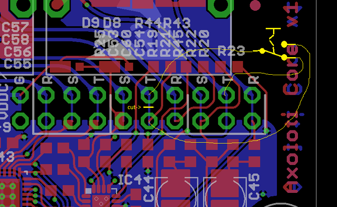
#4

The top row of "RST-STR-STR" pads connect to the headphone, line out and line in jacks. R=ring/right, S=sleeve/ground, T=tip/left. The bottom row connects to the circuitry. Tiny traces on the bottom side connect the top row to the bottom row.
For a mono bypass switch, you need to cut a trace on the bottom side (while the picture is a TOP view, traces on the top side are in red, traces on the bottom side are in blue).

This configuration switches the left line output channel from direct input to output. It does not disconnect the input electronics when off, so it will still "load" the signal source when switched off.


I haven't tried this myself. Actuating the switch may cause a click sound - like any other true bypass stompbox.


#5

i don't want to argue with that, but that statement is just wrong. you don't NEED a true bypass switch to use the axolotl as guitar effects processor. you don't even need true bypass for any guitar pedal. there are pros and cons for any bypassing system...

that aside, if you want TRUE true bypass i would not use the internal jacks but use gavins suggestion. why do you need to use the internal jacks? surely you want a case for the axo when you use it as guitar pedal, so why not just use new jacks?


#6

The picture Johannes has provided is your only option, as it is from a previous post that from what I believe worked as shown. Just cut the track between the 2 solder points.

Nice to see another Axo user for guitar effects.

If I could slightly go a little off topic, can I ask @lugiger, what other analog effects you intend to use ?
The reason I ask, so far in my use the only guitar effect area that DSP guitar effect systems lack, is in the realm of Overdrive. I have heard of other DSP effect systems solving this by incorporating an analogue Overdrive circuit, this is something I have been thinking about, so I am interested in how others may use other analogue effects with the Axo.


#7

just be aware, that this is not true bypass. this is what johannes refers to when describing the load of the signal source...


#8

Thanks a lot for all the responses!

Yes, the way it is shown in the picture is not true bypass, but if I also cut the connection between the solder points on the input, and then use a standard true bypass wiring using a 3PDT switch it should work fine. I will try to make a picture as soon as I'm done.

@Gavin , I think I will keep all my pedals in the beginning, and then try to get rid of them step by step. So the first thing I will do is getting rid of my delay/reverb pedals(which are digital anyway) and then try to patch some fancier effects :D.
But yes, I think I will keep most of my distortion/overdrive pedals and also, I have a Moog MF Boost at the beginning of my pedal loop which I leave ON all the time to boost the signal.


#9

Indeed my sketch is not true bypass, and true bypass can be indeed be done too by switching the input too.

Input bypass is in my opinion only relevant if the input comes from an un-buffered guitar with a passive pickup (eventually also through passive A/B switches, or other pedals with true bypass).
With your MF Boost pedal on, I'd not be concerned about sonic changes cause by input "load", but more concerned about extra clicking noise introduced by the switch.
I'd wire one pole of the 3PDT switch to a GPIO of axoloti though, to be able to process the switch state. If you do a delay/reverb, you may not want to get the reverb/delay tail of sound before switching the effect on.
Just my humble advice, I have not tried this.


#10

That's a good point, thanks. I will have to test how annoying the click is..
If its too annoying I'll probably change the setup again.
But the idea with the GPIO is great! I will definitely do that.