Using a Due is an option, definitely. I'm prototyping something that I hopefully will be selling commercially, so I need to find a way to minimize costs a little bit. Having to put both an Axoloti and a Due in each machine doesn't seem very cheap in the long run, but for prototyping it's a fine idea. I sent an email to Johannes asking if he would be interested in some cooperation, and how it works out in terms of copyright using his machines in a standalone device. Does anyone here know ? It's off topic, I know
SPI/I2C OLED display
He's not just supposed to control monitors.
I only use the small one to get information about parameters. Visual feedback so to speak.
Is there any trick to change the orientation of the oled display? It is working but it fit better in my enclosure if I invert how it show the lines. Thanks!
Well, no.
If you really need to do it, you will have to change a good portion of the OLED object's code.
I've used that touch screen with a teensy, it's a nice screen. Not sure the Due can update as fast as you want, you should double check. the teensy 3.1 was an improvement compared to 2.0 for example..
The due runs at 84MHz, i think it will be enough for managing the display and MIDI controls and sysex.
I ordered two displays through AliExpress, the pictures showed a select option on the back side. But when I received the displays, it turned out there was no option at all. Got the same display types as you and @servandisco. Did you find an option to change the address? I left a feedback note at AliExpress, i hope they will send instructions.
sorry, i did not take that any further. but i have programmed an object that allows me to show and change more than one parameter per row so i was happy with that 
I haven't tried but me and an electronic guru I know bet that to change address you just have to move the o ohm resistors just next to the pins.. maybe both? and given the fact that they are 0 ohm, maybe it's also enough if you just "manage" to remove the resistors and then do test connections using just a drop of solder..
Glad to hear that you sorted things out without using a second display 
For me - the search continues!
I think so too. On this page you can read about a project (using a different type of display) where the address is set using a wire from the DC pin to GND (0X3C == 0X78) or VCC (0X3D == 0X7A). I know this case is different, but it gave me some clue. Given the fact there are two 0 Ohm resistors may imply that there are four possible addresses. I will go and test, but first I have to wait for my breadboard and some resistors to arrive.
[edit]
After a closer look, it seems that moving both resistors must be sufficient indeed. The top resistor from GND to VDD and the other one from VDD to GND, When I'll get to it, I will post the result here.
I do not have these ones,
I think that you have to make the changes @Cannonball shows so that it works in I2C mode.
SDA on PB9 (maybe with pullup resistor)
SCL on PB8 (maybe with pullup resistor)
VDD on VDD
GND on GND
I don't know about the naming on your OLED, maybe it is similar to https://sebiik.github.io/community.axoloti.com.backup/t/spi-i2c-oled-display/638/97
Hi, I added some updated OLED objects.
The new tiar/HW/OLED128x64nice is nice because it will be nicer to other hardware connected to the I2C. (hence with this one, the presence of an factory/i2c/config object is mandatory).
If you have two OLEDs connected with different I2C addresses, you can use two
OLED128x64nice objects.
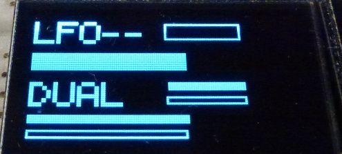
modes:
- mode 0: 4 lines of 11 characters (or "bars", see below).
- mode 1: 1 line of 11 chars and oscilloscope.
- mode 2: full height oscilloscope.
The tiar/HW/bar object connects to a line input of the OLED128x64nice object and make it draw an horizontal bar. If the tiar/HW/bar input is positive, the bar will be filled. If the input is negative, the displayed bar will be hollow.
The tiar/HW/bardbl object draws two bars.
The tiar/HW/strbar and tiar/HW/strbardbl writes a 5 character string before the bars:

@SmashedTransistors just tried those new objects, great! thanks so much for the bars and full scope mode!!!
Argh... still got a bunch of displays lying around here, which I never got installed.......
Just too scared to try to install them, seriously afraid of breaking another board.... 
No, not by adding OLED, it was something else. Dont really know what happened to the board. I have one more now that has got the "low output issue". I am thinking this one can be fixed by adding a resistor or something, I read about that somewhere. But again, I rally dont like to tinker with these things cause its so easy to break, if you dont know what you are doing. And I really don't, when it comes to the hardware side.
I have very very little experience with building hardware stuff. I did build one of the Modular thing Axo control boards, which worked great........... for while. But after a while I started to get a lots of humming from the main output on Axoloti, so I had to take the Modular thing board off again and then the humming stopped.
So back to square one.
For the OLEDS I havent even tried. I got 5 of them, but I just cant get myself to do. If there was a video of someone who did the whole thing I would feel comfortable trying, but al the info is in bits and pieces, so havent really tried.

