Scalextric controller to Axoloti (coil 45 ohm)


#1

Hej!. I'm doing an installation in which Scalextric controllers are controlling the cars itself and also lights and sound.. Initially I was going to do that in puredata but after several unsuccessful tests, I want to give it a try in Axoloti.
since scalextric controllers are very low impedance (45 ohm), and they are actually a variable coil, not a proper potentiometer, I thought about putting PWM through them and see what happens.. Anyone has any advice / trick?

Update: .. I got something just a bit noisy even after kfilter / lopass

greetings!
Ser


#2

A small capacitor between the analog pin and ground, as close to the board as possible, might help you with the noise, specially if that noise is due to the long cable. Maybe a .01uf capacitor would do, or something around there. Do you have any schematics? I might be able to give some tips if I see them. Is it a digital track or is it like the old analog ones?

I don't really get how PWM would help you. Are you reading the controller input and then sending PWM out as if it where the controller? It might be better to read the voltage right from the track, because with such a low impedance, it might be hard to give it a large enough range in a voltage divider for the adc without putting too much current on the pin. You'd have to convert the voltage to axoloti levels, though. Or, maybe you can hack the controllers and replace the coil with something friendlier? You can also try to condition the signal from the controller and try to adjust the adc reference. Choosing the right solution really depends a lot on the details. :slight_smile:

I think I might be able to think something if you share some schematics, or some more details about the electronic parts of this project.

Hm, also, what kind of problem did you have with PD? Was it getting the data to PD, or was it something inside PD? I love PD, I use Purr Data version, because it still gets a lot of attention from its creators. If it isn't something too complicated, I might be able to help you there. :slight_smile:


#3

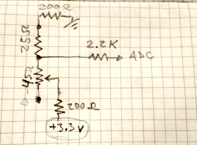
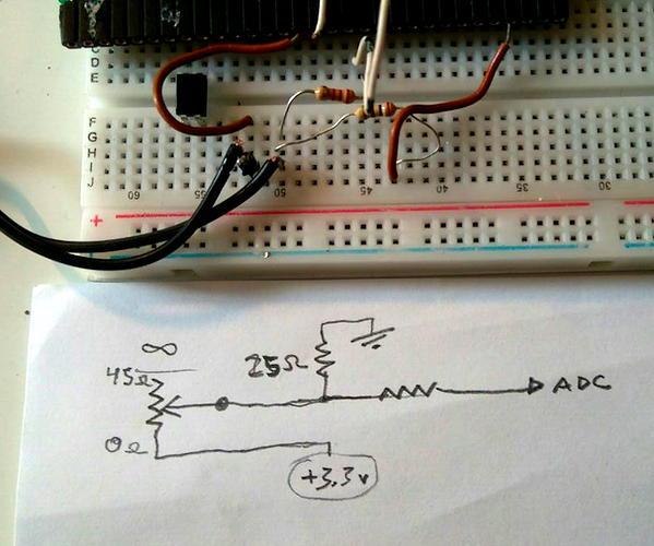
Hej!. I kind of managed. Even without capacitor but then I'm applying interpolation in Axoloti. I added a 27 ohm resistor in order to make a voltage divider and then a 2.2k resistor before the Axoloti Gpio.

With pd there wasn't really a problem. It was the Expert sleepers Es-8 interface I was "imposed" to work with.. IT seems to be an interesting hardware but it can't beat an Axoloti getting sensor data.. Now something I have to test is if I can connect 4 scalextric controllers and "go bananas" with them to see if the amount of midi information disturbs the operative system.. I have a korg nanokontrol and if I move all the faders quickly, PD seems to deactivate it until I reload the "midi-dialog".

But thanks for your tip though.. I will check with the capacitors

greetz!


#4

Hey, no problem :). Ahm. One more thing though: With such low resistor values, that divider is consuming at max resistance around 70 mA. I don't know the minimum resistance the coil gets to, but as it approaches zero, it could be using up to around 185 mA. So, that multiplied by 4 could be too much for the axoloti. I think it would be fried, but I'm not sure, one would probably have to see the data sheets from the regulator and the processor. So I would advise you to be careful going that route :).

On the midi stuff, what OS are you using? One time I had problems in Linux with usb buffers getting clogged, but I think we solved it compiling the kernel with some options. Anyway, I think that won't really happen with the Axoloti, because its krate is 3000 hz. If you are sending one message for each control, you should be sending a maximum of 12 messages each ms, which doesn't seem like enough to clogg the usb pipes.


#5

Hej!.

but that's where the 2.2k resistor I have before the gpio will help to reduce the intensity, right?

I'm on OsX for this installation. and Axoloti works amazingly well and smooth.. The only component that gives trouble is a korg nanokontrol. If I move the faders too quickly. pd "kicks out" the controller and I have to reload the midi preferences with a message.


#6

The 2.2k resistor will help protect the Axoloti GPIO input from large voltage spikes, but it will not limit the current through the controller and 25 ohm resistor. If you look at your schematics, you've got a path from the 3.3V supply via the Scalextrix controller, then via 25 ohms to ground. So with the Scalextrix controller at maximum resistance that's 3.3/(25+45) = 3.3/70 = 47 mA, and with the controller fully activated its resistance will be nearly zero, so only the 25 ohm resistor will be in circuit, so 3.3/25 = 132 mA.

I don't know how much current the 3.3V line on the Axoloti can supply, but it sounds like a rather large drain to me.

Unfortunately I don't really have a good suggestion. The only thing that comes to mind to me is to increase the 25 ohm resistor to something much larger like 1 kohm, which will of course reduce the output voltage swing from the sensor circuit, which will then need to be amplified using an opamp to bring it up to a useful range for the Axoloti ADC input.


#7

So, theoretically if I connect 8 potentiometers without additional hardware and max them out I'm also drawing so much power from the Axo?.

I tried for a bit to have the four controllers full on and Axoloti wasn't complaining about running out of juice.

Anyway. Thanks a lot for the heads up!, I will carry with me an extra Axo and some extra resistors in case I have to make some changes.


#8

how is that? what value potentiometers?


#9

Sorry, Ricard's values are right, I did it with 5v. Normal potentiometers shouldn't be a problem if they are connected to both ground and positive (so that one resistor goes up when the other goes down) because they are usually at least 5kohm. so each would use around .66mA of current. The problem with your divider is that it has very low values, so it lets pass a whole lot of current, also, one of your resistors is fixed, so it doesn't goes up when the other goes down. If you do what ricard says, you'd use a lot less current, but, also your voltage would vary a lot less: it would go from around 3.18v to 3.3v. There are two things I can think of to handle that small voltage range:

-One: you can bring the minimum of that range, 3.18v, to 0. Then, use a opamp to amplify that signal. You could maybe use another opamp to substract the 3.18v, but I think it would have to be another opamp, I'm not sure really.

-Two: you could try setting the adc's vref - to 3.18 and the vref + to the normal 3.3v. Maybe that would work, although it would certainly be more susceptible to noise. Also, I'm not sure if the Axoloti exposes those pins.

I think you already have a voltage divider that works in the tracks that can handle that amount of power, you'd just have to use another fixed voltage divider to bring that voltage to a 0-3.3 range and maybe a series resistor to limit current if you think you need it. I don't know, it seems easier to me.

Edit.
PD
I suppose nanokontrol must not have a limit of messages per ms so it cloggs the usb buffers. Now that I remember, we solved that problem in Ubuntu by forcing it to use USB 1.1 for whatever it's worth, I don't remember why it solves it though. Anyway, that should never happen with the Axoloti and four controls, because it has a self imposed slow time cycle to do stuff; you'd need to send a lot more controls; like, hundreds I believe.

Also, did you try pressing the four controls at the same time? If you do it, I advise to do it carefully. Also, consider if you'd use power for some other things; like audio or screens; it all adds up. And, finally, I'd really advise to try this things in a circuit simulator first. There is this one that's very simple: https://www.falstad.com/circuit/ There are others that are better, with SPICE, but with a learning curve, like http://www.partsim.com/simulator. Any of them could give you an idea of the power your circuit uses.


#10

Sorry for the double post! Actually, on the solution number one, you wouldn't need to substract 3.18v if you connect your control to ground instead of positive. Then voltage would go from 0 to .15 and you'd only need an opamp to amplify the range. Also, consider that with a fixed resistor, your values are not linear, but logaritmic (like a curve on a graph instead of a line), so, unless your variable resistor also has a logaritmic response to pressure, you probably should do some math inside the axoloti to get a responsive result.


#11

Hej guys!. Thank you for the heads up!. Is any of you going to be in Milano during the salone del mobile next week?

what about this circuit? Maybe adding two 200 ohm resistors could make the circuit safer ?. (and still balanced in a way..) Other option I could do it's to use pwm to feed the circuit rather than 3.3v. I tried already and it was working but I have to admit that I have no idea how much that draws...


#12

The problem with that is that, although you are augmenting resistance, you are still reducing the voltage range. There it would go from 1.58v to 1.75v. That means that you only would have around 80 steps on the adc readings. Really, it's considerably less because of noise and the ADC's ENOB (effective number of bits). Also, in certain parts of the pressure range you have a lot less definition, because, like I said, your voltage progression is logaritmic. Only you know if that's enough.

It shouldn't be too hard to use an op amp: LM324 are very cheap and they include 4 opamps. If you add a couple of resistors, you'd had the circuit you need. There are two caveats: one is that LM324 has a max output voltage of positive minus 1.5v, but that is probably still enough range, from 0 to 1.7v. The other is that you'd have to connect your variable resistor to ground instead of positive (and your fixed resistor to positive), so that the minimum output voltage is 0.

There really isn't a way to have more definition, to use less power, and to connect the control to the axoloti without some gain adjustments. You are a victim of the very small resistance on your controllers.


#13

at the end I'm using pwm to drive the coils and seems to be fine.. Axoloti it's amazingly robust.


#14

check here to see the biggest Axoloti enclosure to the date.. : https://www.instagram.com/explore/tags/polestarintothelight/