Rotary Encoders


#1

What is a Rotary Encoder,
Also known as a “Shaft” encoder, there are many versions that operate under this name.
The type I am referring to here is a mechanical device that generates two switching pulses 90 deg out of phase from each other.
The number of pulses per revolution varies depending on brand and make etc.
Two common examples are,

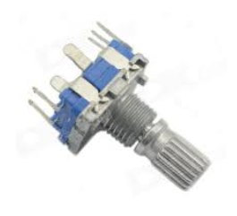
The following example is the bare bones encoder. These come in 2 types, a 3 pin and 5 pin.
Below shows 5 pins, the extra 2 pins shown on the other side of the device, serves as a momentary switch which is activated by depressing the shaft.
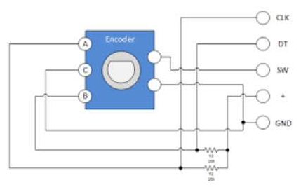
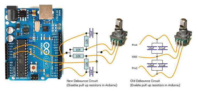
If using this type, it is recommended to apply a simple circuit for preferred operating function.
(circuit shown below A, B and C for rotary function, the other 2 for switching, just omit the switching section for a 3 pin encoder)
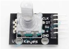
The following type is a 5 pin encoder already soldered onto a circuit for preferred operating function.
As you will see, it even shows what to plug in.
Both versions are plentiful on website online, and may even be available in your local electronics store.
Especially note if you require it to have the momentary switch option.

One difference you may notice between the two versions is the shaft design.
The bare bones version shows a slotted shaft with a threaded base for mounting into hardware, the soldered circuit version shows a “D” shape shaft with no threaded base, but has two mounting holes in the circuit board.
Be mindful of this when purchasing your items to ensure it meets your mounting requirements.

How do they work.
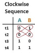
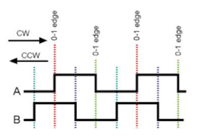
The below diagram shows the workings by depending on the direction the shaft is turned, when signal “A” received a rising edge,
It reads wether signal “B” is either HIGH or LOW.
In the diagram below, when signal “B” is HIGH, it is turning clockwise, when signal “B” is LOW, it is turning anti-clockwise,
Connecting to the Axoloti
This connecting a rotary encoder to the Axoloti will require two digital GPIO Input pins to read the rotating value,
And one additional digital GPIO pin to read the momentary switch if you choose to connect one.
Based on the encoder and circuit images above, connections are described as follows..
CLK – “Clock” used to trigger the rising edge.
DT – “Data” used to determine the direction delivering a HIGH or LOW signal during CLK rising edge.
SW – “Momentary Switch” depending on your encoder you may or may not have one.
+ – “Voltage Supply” With Axoloti this is 3.3v from a supply pin.
GND – “Ground”

CLK, DT and SW will each require their own digital GPIO pin, with “+” and “GND” connected as standard to 3.3v and GND pins.
Be mindful of using any analogue pins that you may require for any analogue readings.

When selecting the pin number in the GPIO digital Input object, be sure to select as “PULLDOWN”

The Patch, Object and Code
This section could go into various directions and create multiple debates about certain setups.
There are many de-bounce concepts, acceleration methods meaning the faster you turn the encoder, the higher the steps, and also many interrupt methods to support these ideas.

I will focus only on what appears to be the most common basic code setup which is how the object “Rotary Encoder Basic” is coded.
Rotary Encoder Basic.axo (1.1 KB)

Giving you the option to make whatever changes meet your needs.

Add the GPIO digital Input objects for the pins connected to “CLK” and “DT”
Object contains two inputs “trig” for the rising edge trigger, “dir” for determining the direction it is turning.
In the Patch, connect object connected to “CLK” to encoder object input “trig” and “DT” to “dir” respectively.

Contains only one output which is the current changing value weather decreasing or increasing.
The output can be connected to an Factory/disp/“i” object to display the value.

You can either modify the object used in the above explanation, or use the following code to help develop your own object.

Inlets:
Inlet_trig – (bool32.rising)
Inlet_dir – (bool32.rising)

Outlets:
Outlet_o – (int32)

Local Data:
int encoderPos;
int encoderLast;
int inval;

Int Code:
encoderPos = 0;
encoderLast = 0;
inval = 0;

K-rate code:
inval = inlet_trig;
if ((encoderLast == 0) && (inval > 0)) {
if (inlet_dir == 0) {
encoderPos--;
} else {
encoderPos++;
}
}
encoderLast = inval;
outlet_o=encoderPos;

Summary
Now that you have the basic setup, you can modify to whatever meets your needs.
You will see over time various versions appear in my contributions once it is up and running.

Some things you may want to consider,
- Minimums and Maximums.
- How to apply presets.
- Increment / Decrement size.

Endless encoder
#2

Thanks for a great introduction!

While porting the Axoloti to the Audiothingies P6 I wrote an object which handles this type of encoder. It has the additional feature that you can configure whether you want one output step per rising pulse on one channel, per falling pulse on one channel, or per rising or falling pulse on both channels from the encoder, effectively yielding different output speeds.

Another feature is that it synchronizes its internal state with the encoder, so that you don't get any ghost movements as soon as you start a patch due to the encoder not being in the state expected by the object.

The output is in the form of pulses: one output gives a pulse when the encoder is rotated to the right, and one to the left, and a third one for either direction. If you want to increment or decrement a value, you need to connect the outputs to a counter. The 'step' output can then be connected to the 'clock' input of the counter, and one of the 'up' or 'down' outputs to the 'direction' input of the counter.

No acceleration has been implemented, personally I like having a high resolution from the encoder, rather than acceleration, which always gets unpredicatble at some point.

(I've been meaning to upload this and other objects for the P6 to the contrib section but haven't gotten around to it yet...).

qdecode.axo (1.7 KB)


#3

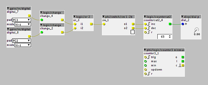
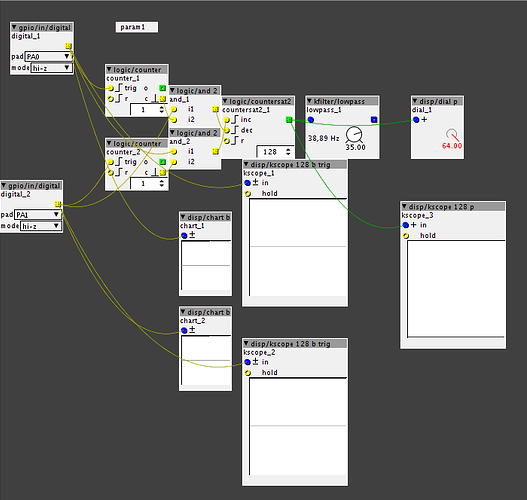
Hi, I'm using this patch encoder inputs.axp (4.0 KB) with hardware debouncing (I want to use just the timer/pulselength object in the future), and it works quite nice, but here is, what happens if I get to the largest value - 64. When I turn the encoder down right after getting 64, it goes immediately to 63, but if i slowly turn it clockwise, the more I do it, the more I than have to turn it anticlockwise before it lowers the value. If I turn it really quickly, the disp/dial sometimes turns red, refusing to go back to normal state. I guess it's a software issue, because it does what is expected at the minimum value. Do you have any suggestions?


#4

The range you want to adjust is between negative - 64 to positive + 64, when you are using a unipolar display dial you should 0.5 increment / decrement. If you swap to a bipolar display dial it will be singular steps, but you will notice that a zero value shows on the bipolar dial as 32. Either way you achieve a total of 128 steps. It all depends on the display you want to use. The easiest solution to your patch above is add in a minus 64 object just before your unipolar display dial. You should get 0 to 64 with 0.5 step increments shown. But don't fret, this is just how it is shown on the dial, you are still using 0 to 128 in your counter. I kept mine this way because I have built it all into internal midi controls so it keeps it all consistent not matter which parameter I connect it to.
Or the other even simpler thing you could do instead, is use an integer display object instead.

About the de-bounce, did you test the difference with or without and notice a difference ? I couldn't so I got rid of it.
:grinning:


#5

Wrong way around.. zero value shows on the unipolar dial as 32 ... :flushed:


#6

I tried interfacing this 24 pulse non detent encoder: https://goo.gl/0X5sSu in a way that it increments each time any of the pins changes a state resulting in a 4 times finer resolution!
The trouble is that I still need to detect the sense of rotation. The easiest way I find is to compare current state of pin A with the previous state of pin B and if it gives logic AND output 1 or 0 it means CW or CCW sense of direction. Right now I have to use a switch for that. I checked different objects but none of them seems to do the trick. Is there any way to patch it or do I need a custom script for this?


#7

I know for 2 x resultion, or you need to do is invert the signal from the pins and have a second set of objects, this way the falling edge will be come the rising edge and it will work fine.
But the challenge with 4 x, is you need the state of both pins to define the direction, not entirely sure, but if you were able to store the state of the last read and do a compare on both normal and inverted signals, you might be able to get there. For now thats all I could think of.
:grinning:


#8

Ok, this is my best solution so far. It's not perfect but I'm slowly getting there :grinning:. When I change the sense of rotation it can change it's value up to three times towards the previous one depending on the internal position of the encoder, because I'm not updating the shift register quickly enough.


#9

I finally got around to uploading my quadrature decoder object to the axoloti-contrib repository, under objects/ricard/logic/qdecode.axo (it is the same as attached to my post above though).


#10

@Gavin -- A question about your encoder objects, if I may.

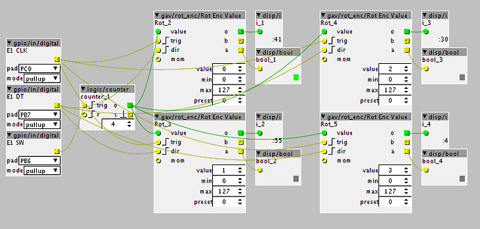
Below is a small section of a larger patch -- this allows 1 encoder to control 4 separate parameters. Hookmod keeps the receiving object from jumping when switching between parameters.

This all works great, however -- it's working more like an analog potetiometer than an encoder. Seems like there should be an input on the encoder object to snap the encoder value to an outside integer. In this case, when I turn the encoder to a value, let's say 32, and then switch away to control another parameter, when I switch back to the parameter set to 32 the encoder value should snap there rather than having to turn the encoder up or down to hit the value before hook releases. That is the point of an encoder, no?

Does that make sense, or maybe I am missing something?


#11

I think you patch is somewhat back to front, but a good attempt anyway.
If you want to control 4 parameters, the easiest way to do it, is to have 4 "Rot_Enc Value" objects, and it is then the link between digital ins to the trg & dir that goes through a demux. Get rid of the hookmods, and logic change. If you are not sure what I mean, I can look into it later for you..:grin:


#12

Thanks! You know, I had started down this path and for some reason I abandoned it in favor of the result above. Could you explain the demux? I was playing around with your objects, and this also seems to work for achieving control over all the parameters:


#13

I only refer to the demux, because it was in your previous patch, and I was not entirely sure of what you were after, but what you have done above is exactly how I designed it to be used. And on a dyslexic side of things, I don't always remember every little detail of what I did when I created the object.
But I am glad you have a use for it.
:grin:


#14

It all works great now. I knew I had to be missing something. Great objects, thanks!!


#15

@Gavin Another question - is there a way to set a default value for each encoder? Would be handy for situations where you don’t want it to load at 0.

Is this perhaps a part of the “preset” box on the value object? (This just occurred to me and I’m not near Axo to test...)

EDIT -- Yes, it appears that's what it is! Putting a number in the preset box outputs that number -1 on patch load.


#16

@Gavin

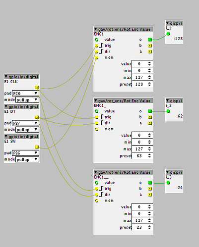
Strange. Testing w/ multiple encoder objects gets me 3 different outcomes:

Any logic? Thanks again...


#17

If I remember correctly, as I am no where near my PC to open up the code, the preset value is always added to the output value, so it is never added to obtain a full integer, it is more of an offset, so on startup, the offset / preset value is added to zero. Now that I think about it, maybe there should be a reset input, to push the output back to preset. Would this help ??


#18

Genuine question: why the preset/add vs just setting the default in the box?

Seems like a reset inlet would be very handy!

Regarding my last post -- it's some sort of processing order issue. Having them stacked gets me different values. Having them all in a row gets me 1 less (0 + preset value) every time.


#19

The reason for adding the preset value to 0 is because of 2 parts..
1 - I already had an object without a preset, so when adding one, I wanted to keep the additional code for feature to an absolute minimum.
2 - To initiate a preset value as a starting integer, a single cycle is required to make it the preset value. So to avoid this extra work, I decided it was easier to just add it as an offset.

Processing order is definitely an issue, and recommend the digital inputs are above the rot_enc objects positioned left to right.

The general order of things is left to right, top to bottom.
So as per your image, The first digital input is first, then the three rot-enc obj split by the int display, then the 2nd digital input, then the third, and it repeats in the same order.

So you want it to read all the digital inputs first, then the rot-enc's to read the inputs and as all three digital inputs would have been processed all the rot-enc inputs will be valid signals.

When you apply the value setting, a counter etc to select which one you are adjusting, you also want the value processed before the rot-enc's are processed, so the selection is clearly identifiable when the rot-enc object is processed.

When I build my patches, I focus on having the objects in groups of the tasks they are doing, and I make every effort to keep the object within each group left to right, and each group below the next. This is not always clear cut and very often exceptions, but for me it helps.

So the digital inputs is one group left to right,
Then the value selector left to right,
Then the rot-enc's underneath left to right.

Its just trial and error, lots of practice etc..
Hope above helps..


#20

This is all GREAT information, thank you!

More like this?

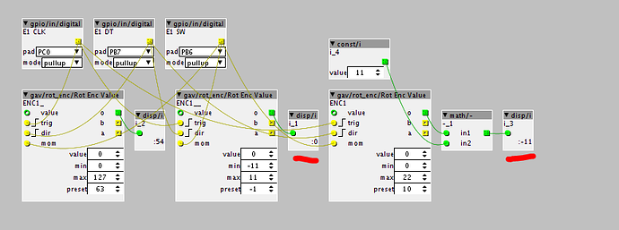
This also brings up another question, hope you're not sick of me yet! I would like to patch one of the objects to control the semi-tune of an oscillator, so +/- 11 steps. In the middle object you see I have set the range from -11 to +11. Works great in theory, but I can't get it to turn down below 0. If I set the present to -12 I get -11 at patch load, but once I turn up past zero it won't go back down into the negative.

It works as desired on the right, but would prefer to have less objects if there's something I am missing.