Protecting Axolotis IO from high currents


#1

Hello everybody,

first post here in the forum after looking around for some weeks and reading lots of articles.
Loving the Forum, loving Axoloti!! Great job Johannes!

Anyways, I was wondering what the best way would be to protect the analogue ins from high currents.
I am currently in the process of building an enclosure with pots and some IO jacks. The plan is to use Axoloti as a standalone instrument as well as with my Eurorack system. I want to send CV back an forth between the modular and Axoloti.
I found lots of schematics for op amp circuits to convert the voltages. However I have quite a few Eurorack utility modules already where I can amplify, scale, offset and invert CV signals in every possible way in order to get something useful. So I don't feel the need to build another op amp circuit.
However I'd like to protect my GPIOs and Axoloti from accidentally sending in an unscaled signal like +10V or +/-5V. From my understanding that could really damage the Axoloti Core board, right?
Would a simple circuit with an input resistor and a couple of shottky diodes (bat 48 for example?) be able to protect the board? Like this one:
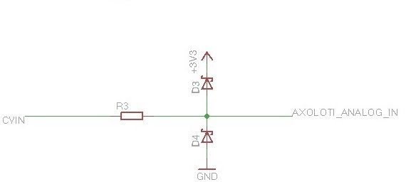
If yes: Do I need to connect the +3V3 to the VDDA, VDDC or VDD?

Last question: Is it possible/ necessary to protect an analogue GPIO output as well?

Thanks in advance for any help and comments.
Happy Monday to you all!!


#2

What value do you have in mind for R3?

If R3 would be 1kOhm, and you feed +10V into CVin, it injects 6.5mA into the +3.3V supply. If you 'd do this on 15 analog gpio inputs, this adds up to almost 100mA in the worst case of feeding them all with +10V. If there is no consumption of 100mA on the 3.3V supply, the linear regulator will not be effective anymore, but the +3.3V supply will lift up, and this can certainly cause damage...
So I suggest to use VDD (not VDDC) as the 3.3V net, VDDC has much less consumption.
And use more than 1kOhm for R3, say, 4.7kOhm.

You can use exactly the same circuit to protect the analogue GPIO outputs.


#3

Thanks for the detailed reply. Really useful infos for an electronic-noob like me.

For the moment I use a 10KOhm resistor and bat48 shottky diodes. VDD as 3.3V net.

I tested the circuit on breadboard without having any GPIO connected. When I feed it +10V I get about 3.6V coming out on the other end and around -0.4V when I send in -5V.
However, I don't intend to send 10V CV to the Axoloti anyway. The idea is to attenuate any CV signals with a passive attenuator (10KOhm Pot) coming from the modular prior to sending it through the protection circuit into the GPIOs. The resistor and diode clamp is just a safety precaution in case I make a mistake. The maximum CV inputs will be 4.

If I use the same circuit for the analogue outs, do I need the resistor as well as the diodes? If yes, in which order?