Potmeter and their range


#1

Hello there all

i have not so much electronic knowledge and not at all programming knowledge and i have a question about the pot meters,i use 10 k ,100k and even 500k meters because i wanted to make the range bigger of the lfo, the midi controller had a much bigger range, it goes from a very low till very high frequency,the gpio doesn't go as much i want,i would love it if it will go from lets say 0.1hz till 233 hz, is there a object our other way to make this possible?

#2

Potentiometer value won't have any effect on range since they're configured as potential dividers. I think I saw 10k recommended as a good value in terms impedance. Is the problem you're having that you can't a full range fractional value out of the gpio object?


#3

Yes exactly 10k is what i thought also, but yeah I have that problem with the gpio, hope there is a way to go around our solve this.


#4

The potentiometer resistor value does not really(*) matter when it's connected as a voltage divider.
Can you observe full range if you connect the "gpio/in/analog" to a "disp/dial p"?
"gpio/in/analog" outputs a unipolar value (only 0 and positive values), to modulate the speed of an lfo to its full range, use "conv/unipolar2bipolar".

(*) within a reasonable range, too low will consume more energy than necessary, too high will make it sensitive for noise.


#5

Great thanks for the quick and clear responses,i will check this straight when i finish work, i didn't do the unipolar converter so i will try this, thanks!


#6

hello there, i tried it and i do work but not yet the range i really want to have,is there any trick for ?sorry for the newbee questions but i love this toy and want to make the best of it hehe


#7

No prob with newbee questions. Please provide a bit more details: what potentiometer value are you using, how is it connected electrically (same as here ), does a patch with "gpio/in/analog" to a "disp/dial p" show you the full range?
Also, double check that the right GPIO is selected in the "gpio/in/analog" object, other channels than the one where the potentiometer is connected will show similar response too but at reduced range and accuracy.


#8

That's interesting. Is that only if they are left floating or is there some bleed even if they're connected?


#9

It's big on unconnected (floating) analog inputs, with very large resistances this effect can also be noticeable, this is why I suggest potentiometer values between 4.7kOhm and 47kOhm.


#10

hi johannes, i tested all the potmeters i have they go into range of 10k till 500k,(the 500 will be replaced by MUCH lower ).With a scope and the converter he showes the full range.


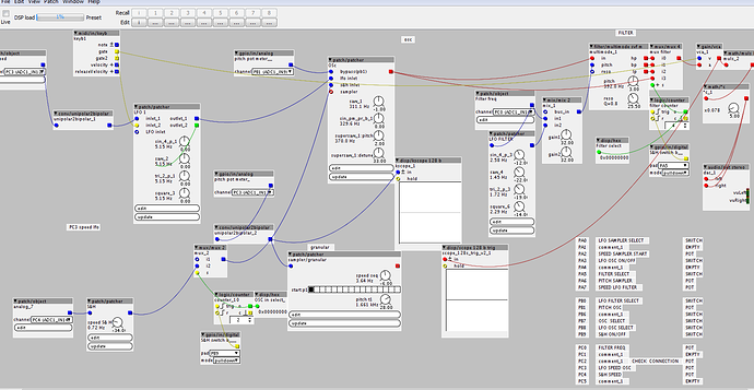
in the image is like you see at the right bottem all the connections.
PC2 PA7 PC3 are 500k potmeters
PA2 = 10 K
PC0 = 250K
PB1 PB6 =100K

hope this is suffiecient information :slight_smile:


#11

now i changed th pach and added some more potmeters and the scope show me only the up 20% in the range i can adjust. The VVD connections are destinated for the gpio's?maybe i overload some VVD ports because i put on gpio from another group? hope i explained it correct


#12

Overload on VDD is unlikely to cause any permanent damage. Connecting VDD to ground would cause the board to stop working, but will work again after removing that connection.
If you select "help" in the object popup menu (little triangle top-left in the object), you get a patch that monitors all analog inputs. How does the response look there?


#13

i cannot look now because im rewiring everything more logic :slight_smile: i hope to finish tomorrow and i will straight check it !also im ordering mor epotmeters 5k and 10k for now,and a demuxer. i will probably have some question about that but i will ask them in the correct tread.


#15

i now wired everything ,and is see that some gpio response same item with others,. This has to do with the way to high resistance potmeters i use?

also some responses are a straight line and some are not,see picture, this is normal or i did something wrong somehwere?
Some pot meters response is perfect in the scope and some only around 10%.


#16

Unconnected input channels "track" the previous input, but noisier and probably not full range, that's normal.

If you swap a "10%" potentiometers with a "100%" potentiometer on the same channel, do you get 100% response on that channel? That would reveal if it's the potentiometer or the GPIO...


#17

i was actually just doing this and solved already one problem, one cable from the ground to th breadboard was not good ,now i have 2 pots left,i will find the solution, if not ill be back :slight_smile: thanks for the help ! i have hope again i will make what i have in mind :slight_smile: hope all is possible!


#18

So some days later and many new routes I would still like it if i could have a bigger range, is this possible with a math object maybe?


#19

Please be a bit more specific:

  • do the potentiometers reach full range when observed in a patch with "gpio/in/analog" connected to "disp/dial p" or "disp/chart p"?
  • "unipolar2bipolar" didn't help?
  • does the actual parameter that you want to control provide the range?

#20

Im sorry ,but on all 3 answers it is yes :slight_smile:


#21

i found a solution, i will use the midi/intern/cc to make the pot a midi CC and then assign the corresponding midi channel to it ,i did it with the LFO amount also thanks to grimmreefers advice :slight_smile: