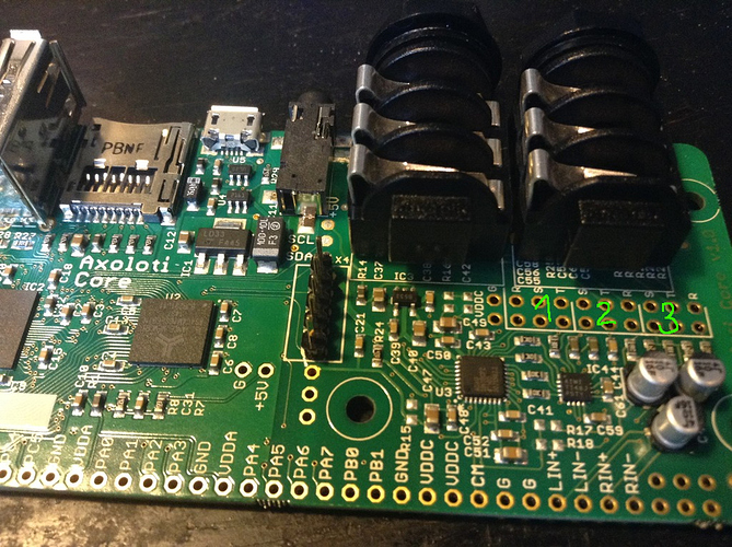
On-Board RST pin outs


#1

Hi, I have question concerning the on-board RST pin outs. If I get it right, they provide the same I/O as the three stereo jacks.
My question is what happens if I connect line level source to the main stereo output pins? (#2 on the picture). Will the source be propagated to the physical jack connector and 'mixed' with actual Axoloti output signal? Or is it completely stupid idea to feed the output jack with additional input signal?

My intention is to use the Axoloti as an master FX unit for another microcontroller based synth, all closed in one box. I could (and I will) just connect it to the input (#3 on the picture) and then pass it thru in the patcher if I want the dry signal. But I thought about adding a physical switch to route it either to Axo's input or straight to the output jack. Does that make sense?

Thanks in advance for any insights!


#2

I don't think this is necessary... the codec used (ADAU1961) has a internal mixer, which allows pass thru/mixing of input to output, bypassing the ADC/DAC... so I think theoretically, it could be done in firmware.

I can't say for sure, as Ive not looked into the full details, but @johannes will know if its possible and if its simple or not.


#3

The codec indeed has an onboard analog mixer that can mix the analog inputs to its analog outputs.
I strongly recommend not to inject line level signals on the output.

'R' 'S' and 'T' mean ring (right), tip (left) and sleeve (ground), 1 is headphone, 2 line out, 3 line in. There are two rows of holes, the top connect to the jacks, the bottom row to the circuitry. On the bottom side of the board there are tracks that connects the bottom row to the top row. You can cut those tracks and get separate access to both the jack signals and the circuit signals.
This is for hack-ability : you could split out stereo into dual mono, or convert the line input jack into an expression pedal input, or perhaps add an volume potentiometer to the line output, or in stompboxes some people require a true bypass...

You could connect your synth to '3', and then call that jack "dry out". Maybe another option is connecting your synth to the jack socket switches of the line in jack. So then it allows to disconnect your synth by inserting a stereo jack.
Or - if your synth is mono - wire it like an insert jack on a mixer desk...


#4

Thank you guys a lot for valuable info! Especially the interruptable traces are interesting feature. I'm tempted to add the output pot. What specs should this potentiometer have? Assuming it should be a stereo one but my circuit design skills are rather lame, so sorry if this is a dumb question.

Concerning the jack socket switches, I noticed that one side of the 3 metal plates is lifted up when the jack is inserted . Are the connector pins on this side those that get interrupted by inserted jack?

My synth is stereo. It's a Goom synth, ported over to STM32F4 board by Thorsten Klose of MIDIBOX fame.
Control surface for the synth is made in PD, running on RPi2 with 7" touchscreen.
That leads me to other question about running Patcher on RPi but I'll start another topic for that.

Thanks again!


#5

For a line out volume potentiometer: stereo, "log taper", and I suggest 1 kOhm to 4.7 kOhm value. (Use linear taper pots for controllers!)
The three plates that lift up actually connect to the jack and break apart from the three that do not lift when a jack is inserted.


#6

Awesome! Johannes, you rock! Thanks a lot!!!

Edit: I'll see if I can find the traces that are to be cut.


#7

sorry, are you saying you don't recommend using the mixer? or to connect the line ins to outs, as cube was suggesting?

had a look at the firmware, and codec specs, looks pretty simple to get the mixing, simply a matter of setting R23/R25,
really bits 0-3, as I'm not too interested in cross mixing left to right etc.

I also had a look at the schematics, looks like you connected LAUX/RAUX to CM... is CM, which is 'common reference output', Im assuming this means they are muted?

perhaps in a v2 board these could be taken to CM and to connectors on the back of the board, such that the traces to CM could be cut if one wanted to use them?
(Im assuming if not in use they need to be taken to CM, which would normally be done by a 'switch' in a jack, and I can understand adding a jack is cost, and also valuable board space - so complete understand the design decision.)
of course, Ive only a very vague idea what I'm talking about, so this could be a ridiculous idea :smile:


#8

No the mixer would be fine if you want mixing analog in to analog out without going through adc/dac. Yes and configuring the mixer can be done in an object, similar to audio/inconfig What I don't recommend is connecting external output signals to the output jack, with the purpose of mixing in the output of something else, this requires output resistors between the line out and jack.

LAUX/RAUX are indeed not exposed, and they are muted. They are not broken out to solder pads, sorry. With surgery they can be cut from CM and wired to something else.