OLED screens and the thonk axocontrol board


#1

So I got an axoloti core in january, and being a fairly basic dude I decided to snag one of the old Music Thing Modular axocontrol boards. I soldered it and attached it and it’s working great. Anyways I want to attach one of those .96 inch OLEDs.
So I’ve been doing quite a bit of looking back in threads, and I’ve gleaned that I’m going to want to attach the pins to vdd gnd pb8 and pb9.
Now from what I can tell those two points are routed to two LEDs on the old music modular board.

My question is, can I just like attach the OLED to those points while the LEDs are there via wire, and Jerry rigging a second connection off the axoloti board? Or will it only work if I disconnect the LEDs and use the pads from the control board?

Also will I have to solder any more resistors to protect the screen since there are 5 present on the music modular board to protect the LEDs? Thanks in advance

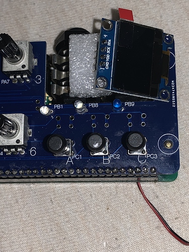
#2

I’m thinking those would be the new solder points, and there are 4 - 1k resistors on the board


#3

PING!
I'm in the same boat and also unclear about this. Do I need to disable the LEDs on the AxoControl board or can I wire the OLED in parallel (and put up with weird LED behaiour, I guess)? Can I (reasonably easily) modify the OLED objects to use different IO (I am a C/C++ coder by day, so I think I have the skill set for this)? If I can modify the code, would anyone care to suggest alternate IO candidates (or list ones that are useful for other purposes that I should avoid using for this)?

Regards,
John


#4

I think I've answered some of my own questions:

1) IPC is on PB8 and PB9, so it looks like those are the only IO that can support the OLED
2) It looks like the LEDS on the Axocontrol and the OLED are mutually incompatible: https://sebiik.github.io/community.axoloti.com.backup/t/axocontrol-build-with-oled-screen-mini-documentary/5358

Hopefully this info will help anyone else who ponders these matters.

Regards,
John


#5

Looks like the designer of Axocontrol made a seriously unfortunate design choice. There are many other pins that can drive LEDs, but he chose the ones that are used for I2C.

A motivated person could cut two traces on the Axocontrol, and wire the LEDs to two other pins. This would also require small modification of the Axocontrol object.

Or use the SPI version of the OLED.


Axocontrol Enclosure
#6

I just got this working. Hopefully the following will help anyone else trying this:

1) The LEDs on the AxoControl are not compatible with an OLED and the resistors used by the LEDs are between the LED and PB8/9, so you cannot reuse them in-place as pull up resistors for an OLED. Since I had already built my AxoControl with the LEDs, I de-soldered the 2 resistors (R2 and R3) for LED2 and LED3 and re-used the pads furthest from the LED for PB8 (Clock) and PB9 (Data) lines to the OLED. I lose 2 LEDs this way, but its a trade I am happy with. I guess I could rewire the LEDs and Resistors to a different GPIO, but I already have enough Franken-wiring happening for my taste. I also breadboarded first (to confirm various connections would work) and determined that I did not need pull-up resistors with the AdaFruit OLED I am using.
2) You MUST include the gpio/i2c/config object (in order to turn on IPC on PB8/PB9) in patches that use the OLED. This is probably obvious to quicker folk, but I expect there are some other thickies like me...

Regards,
John


#7

I2C, NOT IPC. Is autocorrect interfering?

The reason you don't need pullup resistors for the Adafruit I2C OLED is that the STM32 has internal pullup resistors, configured in gpio/i2c/config:

// setup the pins
palSetPadMode(GPIOB, 8, PAL_MODE_ALTERNATE(4)|PAL_STM32_PUDR_PULLUP|PAL_STM32_OTYPE_OPENDRAIN);// SCL
palSetPadMode(GPIOB, 9, PAL_MODE_ALTERNATE(4)|PAL_STM32_PUDR_PULLUP|PAL_STM32_OTYPE_OPENDRAIN);// SDA

#8

Thanks - corrected the object name in my post. I figured the AdaFruit unit probably had built-in pull-ups, I just wanted to clarify that I did not add any when I modded my AxoControl...

Regards,
John


#10

thanks for the tip.

Also discovered that the @thetechnobear 's Switches object will need to have the LED update code commented out or changed to new pins, otherwise patches won't work correctly when used with the OLED.


#11

Yes - any thing that tries to use the PINs that are now used for I2C is going to be an issue. Sorry I missed that.

Regards,
John


#12

just to add - same goes for the A773/axocontrol object that has a smaller memory footprint.
Lush delay with OLED control displays is a challenge right now.. Easier in retrospect to have found a different pin for the LEDs and changed the objects a bit <- for future divers


#13

@tele_player in case of using SPI - how would the wiring look like?