[obsolete] Axoloti PDM microphone


#1

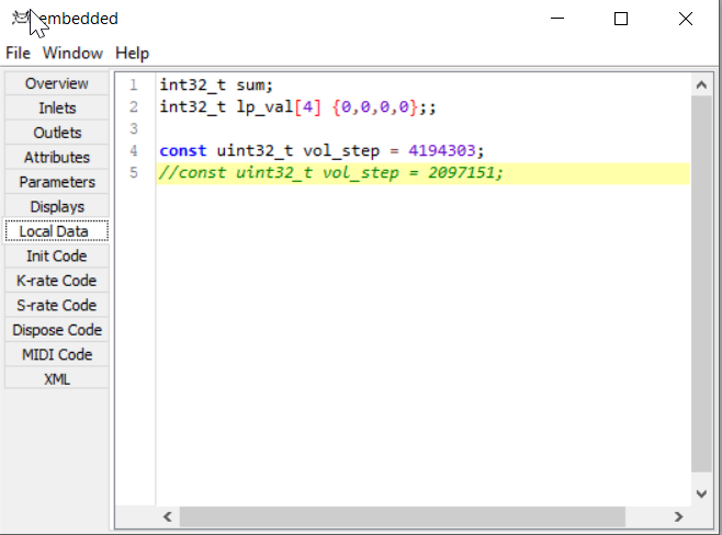
I have made a first attempt to include the PDM microphone on the Noloti into the firmware.

In short, we are receiving the microphone's bitstream at 3.072 MHz from I2S3 (which is basically SPI3) via DMA into a buffer of 32 uint32_t, called "pdm_inbuf[32]". 3.072MHz divided by 64 equals 48kHz. This buffer is made directly available in any custom object.

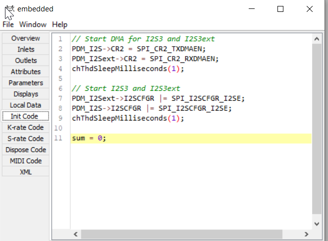
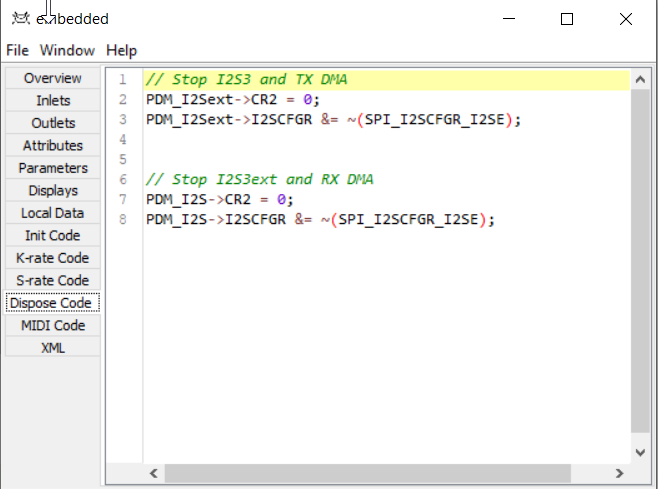
Some registers have to be written in the Init Code to enable the clock and DMA and such, since I only want these to be on if an object actually uses the PDM microphone. (and ideally the registers should be turned back off in the Dispose Code)

Since I am not good at writing filters I get sound but very faint and with a high noise floor.

I even tried linking and using ST's dedicated static library for PDM (pdm2pcm) but it seems too much of a hassle to adjust everything to the overall Axoloti way of running processes.

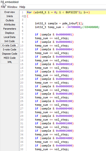
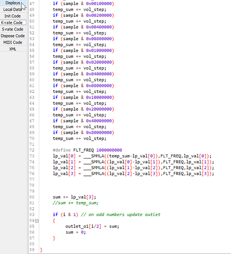
Right now I am going through 32 samples and reading each 32bit sample bit by bit, and for each bit that is set a fixed amount will be added to the decimated "temp_sum". Then two temp_sums will be added together and that will become one of the 16-buffer 48kHz audio samples Axoloti expects.

The repetitive bit compare part of the code (if sample & 0x00000001 etc.) is taken from some "ZeroPDM" or so library code I found online. It looks weird not to do a for loop but you indeed save a lot of CPU by doing it this way.

I am assuming I need a running average that repeatedly reads chunks of 16 or 32 bits, then advances a few bits, then samples the shifted signal again, so that each bit is read multiple times, effectively low-pass filtering the stream.

I did try a version employing a sincfilter lookup table but it didn't sound very good either. I am guessing this is where the multiple count of each sample would come into play?

I am almost embarrased because all I do is 4-pole low pass filter the raw decimated signal with code I took out of the "lp1" factory object.

Does anyone here have experience in properly filtering a PDM bitstream?

Here is what I have so far:

#2

I think your basic principle is ok, but I'm not good enough at signal processing to say what's going wrong.

Basically PDM can be viewed as a one-bit bitstream that needs to be downsampled. So in principle, you need a low-pass filter that runs at 3.072 MHz that cuts off everything over 20 kHz, and after that the signal is decimated by taking every 64th sample. The first step in this is converting the 0 / 1 in the bitstream to -1 / 1, to get a signal that is symmetric around 0. So your += vol_step should have an else, doing -= vol_step when the bit is zero.

A problem here is that since the filter is running at 3.072 MHz it must be very efficient or it will eat a lot of CPU. The designs I've seen use a simplified form of FIR filter called CIC, which is basically an FIR filter with all the coefficients set to 1, which is used to bring the sample rate down to some intermediate frequency, and then another low pass filter is used to bring it down to the final sample rate of 48 kHz. One trick that can be used with CIC and FIR filters when downsampling is that since only some of the output samples are used, the rest don't need to be calculated. But this is already what you are doing when you sum up 32 bits to a single temp_sum - it's basically a 32 tap CIC filter, which has a sinc frequency response.

I think the reason that the other designs I've seen use a combination of CIC and FIR with an intermediate sample rate, is that the sinc frequenecy response of the CIC gives a lot of passband droop if used to do the complete downsampling, which then needs to be compensated in some way. By only using the CIC filter for part of the downsampling, only part of the sinc curve will be visible in the final output.


#3

Thanks Ricard.

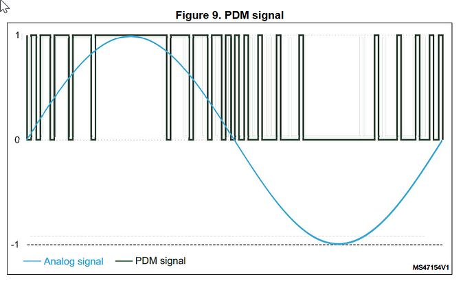
I was assuming that, in theory, if the bitstream has a lot of zeroes it would mean the audio wave is currently at a "negative pressure" value? And if the signal is at its quietest value, around zero, the PDM stream would have a duty cycle of 50%? Am I misunderstanding this diagram from ST's document AN5027? If I got it wrong this could explain the low levels as I am sort of cancelling out the values!

It is not clear from my code - actually one can see in the loop that I declare and initialize the "temp_sum" as a negative value of around minus 34 million ... amateurish but I have been trying to keep everything around unsigned levels and shift it with a magic number until I understand more about what levels are required. Are unsigned ints bad for the filtering part?


#4

Would there be any merit in using a lookup table (that looks like a hanning window)? I have seen this technique in the zeroPWM library, frome where I also took the bit decimation code:

sincfilter[64] is the lookup table I mean. And Adafruit_ZeroPDMSPI::decimateFilterWord contains the decimation code.


#5

The Noloti has a PDM microphone? Was this mentioned anywhere else?


#6

You're right, looks like this was not mentioned in the other thread. Yes it does have a PDM mic on board, normalled to SPI3 via PB3 and PB4 but a jumper can be cut to disconnect the mic from power thus release the pins.


#7

This is now obsolete. On the newest prototype the PDM microphone now connects directly to the codec. Let's have the hardware do the filtering.

See the second half of this post: https://sebiik.github.io/community.axoloti.com.backup/t/new-axoloti-prototype/7970/53