Noisy analogue input


#1

Hi there,
I tried several analogue inputs and all of them are very noisy. My config is just a simple pot (extreme pins go to VDD and ground, and central pin goes to analogue input).
The result is extremly noisy. Do I need to insert a caps in somewhere or else ?
on another hand is it possible to display the 12bit datas, the analogue object is blue and only permits display of 7 bit...

Thanks


3 Noob Questions abou connecting Potentiometers
#2

What value pot are you using?


#3

from 100 to 1Mega, always the same noise.


#4

Too high. Try a 10K lin pot.


3 Noob Questions abou connecting Potentiometers
#5

sorry if I was not clear: I tried from 100 ohms to 1 Mohm, with 1k, 10k, 100k


#6

"disp/dial p" shows quite a bit more than 7 bit. If you're familiar with hexadecimal, "disp/hex" will show you the internal value.

I do not expect them to be extremely noisy, though. What's the range of variation you're seeing for a constant potentiometer position? And can you verify the gpio/analog/in gives you (close to) the full range when moving the pot from left to right?

I suggest a potentiometer value of 4.7kOhm to 22kOhm, with a linear taper (not log or anti-log). And use VDDA rather than VDD as reference for analog inputs.


#7

Yes I tried vdda , but there is no change.
Noise is on the total range of the input, this is not something I can smooth. When I turn the pot there is a little change, noise in the upper midrange or noise in the lower mid range if the pot value is 0 or max...


#8

Could you post a picture of your setup? Just wanna rule out a few things.


#9

ok, I tried with some new cables and it is much better.
I still have some noise on the input, it's about a range of 0.3 when I inspect with the dial display. When I connect to a mere Oscillator like a sine I can hear that noise, the freq quency very instable.. Here is my setup:


#10

The way you put cables in the solder holes is probably not making good contact.
I suggest to solder a female header in the gpio solder holes if you want to plug in prototyping cables.
The reason there is no female header pre-assembled is that there are many different options: board-to-wire connectors, screw terminals, male headers, female headers, and it's much easier to solder a connector than to desolder one.


#11

Yes I tried to solder directly on the board but change. I tried changing the power supply from USB to standalone power supply but no change either.
Can it be a defectuous board?


#12

Seems unlikely since you saw a great improvement with the new cables. So to be clear, your cables are now soldered to the axoloti?


#13

yes, cables soldered to axoloti on one hand and soldered to pot ( tried various pots too) on other end.


#14

A 10nF capacitor between GND and the analog input could reduce noise. Defectuous board, very unlikely, it 'd make no contact.


#15

It is even worse with the capacitor.


#16

Any suggestion ?? the setup is very simple it should work without any problem. i cahnge all components and it still make noise on the input..


#17

Hi,
Just to make sure if it was from my setup or material: I unsoldered everything and just measured voltage with multimeter. Between Ground and vdda it's 3.24 V, but between ground and PA4 (or any other output pin) it's noisy.
By the way PA4 in output mode works fine. Don't understand why it works on output mode and not on input..


#18

I observe 0.03 units noise from a gpio/in/analog on a disp/p.
I don't hear objectionable pitch noise when connecting gpio/in/analog to osc/sine...
Are you sure you have selected the right input in the gpio/in/analog object? Because the next input channels will also follow the previous one if they're not connected to a source (but in a noisy way).

If you create a gpio/in/analog object and choose help from the object popup menu, (or menu help->library->gpio->in->analog), that patch shows all analog channels at once.

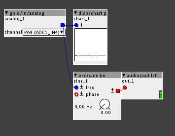
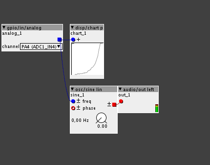
Maybe post screenshots of a gpio/in/analog connected to disp/chart p, one without touching the potentiometer, another showing the full range of rotation of the potentiometer?


#19

The noise on input is about 2 units.
I tried on all analogue inputs from PA0 to PC4 but still the same problem. When I look at help object it shows movement on PA4 PA5 PA6 PA7 PB0 PB1 PC0 PC1 (when physicaly conected to PA4). All are noisy.
Here are the screenshot, without touching and full rotation:


#20

How noisy are the voltage readouts in the main Axoloti window (5V and VDD)?
I suggest to use "osc/sine", not "osc/sine lin" for better mapping, using "osc/sine lin" (and a linear potentiometer rather than a logarithmic one, I suspect you're using a log potentiometer from your screenshot) I do get noises too, that's because the resolution of the analog input is not used efficiently that way.