yes, cables soldered to axoloti on one hand and soldered to pot ( tried various pots too) on other end.
Noisy analogue input
A 10nF capacitor between GND and the analog input could reduce noise. Defectuous board, very unlikely, it 'd make no contact.
Any suggestion ?? the setup is very simple it should work without any problem. i cahnge all components and it still make noise on the input..
Hi,
Just to make sure if it was from my setup or material: I unsoldered everything and just measured voltage with multimeter. Between Ground and vdda it's 3.24 V, but between ground and PA4 (or any other output pin) it's noisy.
By the way PA4 in output mode works fine. Don't understand why it works on output mode and not on input..
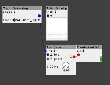
I observe 0.03 units noise from a gpio/in/analog on a disp/p.
I don't hear objectionable pitch noise when connecting gpio/in/analog to osc/sine...
Are you sure you have selected the right input in the gpio/in/analog object? Because the next input channels will also follow the previous one if they're not connected to a source (but in a noisy way).
If you create a gpio/in/analog object and choose help from the object popup menu, (or menu help->library->gpio->in->analog), that patch shows all analog channels at once.
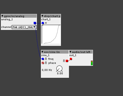
Maybe post screenshots of a gpio/in/analog connected to disp/chart p, one without touching the potentiometer, another showing the full range of rotation of the potentiometer?
The noise on input is about 2 units.
I tried on all analogue inputs from PA0 to PC4 but still the same problem. When I look at help object it shows movement on PA4 PA5 PA6 PA7 PB0 PB1 PC0 PC1 (when physicaly conected to PA4). All are noisy.
Here are the screenshot, without touching and full rotation:

How noisy are the voltage readouts in the main Axoloti window (5V and VDD)?
I suggest to use "osc/sine", not "osc/sine lin" for better mapping, using "osc/sine lin" (and a linear potentiometer rather than a logarithmic one, I suspect you're using a log potentiometer from your screenshot) I do get noises too, that's because the resolution of the analog input is not used efficiently that way.
The voltage readouts are stable. I changed to osc/sine but it's still noisy the same way.
Yes in my example it was a log potentiometer, I but tested with linear pot, and brand new. log or linear still the same.
OK, in a last attempt I just changed the cables. And it's much better !!!
I still have a little noise which make the sine wave a little grainy. Capacitors between input and ground make it worse. Maybe it is possible to smooth it with an object ?
Nevertheless when pot is at max value , there is noise, as much as before, but only when it reaches the last degrees of rotation.
Thanks for your patience
It's getting better now ! I just soldered the capacitor directly on the axoloti, and I use a kfilter object to smooth everything.
Have you tried grounding the adjacent analog input pins? All those unused traces / terminals can sometimes act as antennas that pick up more noise.
im having th same problem,
im using:
- 10 x 10 K linear pots
- all is grounded
- 2 switches (on ground ,before vdda,no differnce)
- 4 rotary switches,only 2 really connected with the resistor chain,2 are connected to ground,vdda and gpio(before not connected ,no difference)
- there is nothing disconnected
- everyhing is on VDDA
it is quite important because i control the dial matrix with them,and everytime i switch to another carrier what i want to modulate,he automaticly goes to the value what i had before,just because he wiggles a tiny tiny bit.
I believe excessive noise is not your problem here, but the dial matrix reacting on every tiny change. Please start a different topic (or reply to an existing topic if it exists) about this dial matrix business.
Hi, I'm digging out this old thread as I was looking for ways to reduce potentiometer noise before I finally start building an enclosure for my axoloti. It's going to be out of wood, so I'm going to shield it with copper tape on the inside like described in this thread.
To further reduce noise, how important is adding capacitors?
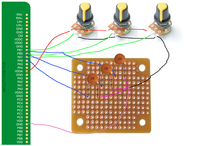
I also don't really get this - would I solder a wire from the center pin of a potentiometer to an analog input and then another wire from the input to the capacitor, then to GND?
Could only one capacitor be used for all of my 15 potentiometers?
Thanks. Just to make sure that I don't screw this up I made a sketch of how I would do the wiring:
Would it work like that?
Also what kind of capacitors do I need - are these ok (10nF ceramic capacitors with 50V rating)?
yep, looks good. you can also solder the capacitor across the potentiometer, from ground to middle pin. or directly from the axo input to ground. it depends a little on how long those wires from potentiometer to analog in are going to be. i would say, try on the pot first(easiest), if you still have too much noise, move them closer to the board.

