New Axoloti prototype


#1

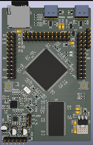
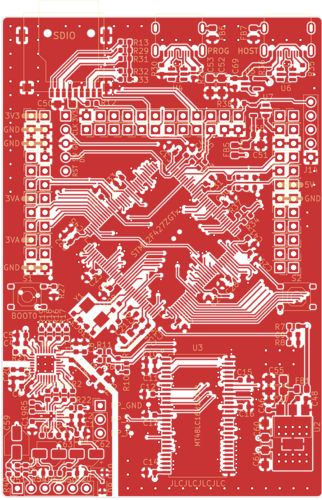
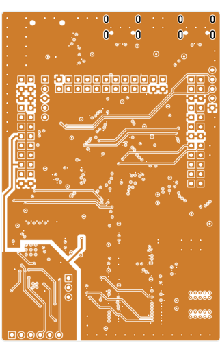
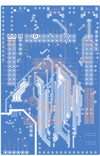
Hoping that some of you good people are experienced in PCB design and I am hoping to get some feedback on my new Axoloti prototype. Currently I am mainly concerned about the SDRAM connections: trace lengths vary between 31 and 58 mm, which from my research should be okay given the "low" clock frequency under 100 MHz.

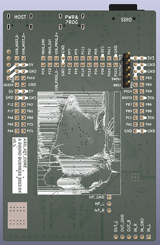
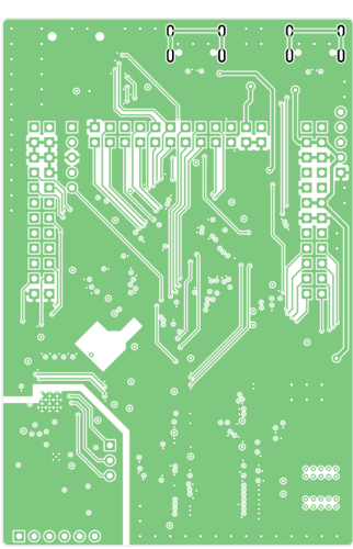
This is a 4-layer board in the stackup SIG/GND - GND - GND - SIG/3V3. Unusual but I felt the high speed SDRAM traces on the bottom layer do need a good GND reference plane on layer 3 and routing power just by traces seemed a bit messy so I put a power plane on the bottom layer. Putting GND there would have allowed for better shielding I guess but you always need to compromise.

Overall I feel like I made many "not sure if necessary but don't want to risk it" choices, e.g. all the ferrite beads and the separate AGND and 3V3A planes for the audio codec section.

Any thoughts?


#2

Schematic in in PDF format here.


#3

While I can’t claim any knowledge as an electronic expert at all, I would like to leave some words of encouragement for this initiative!


#4

Thanks! We'll know in a few days how this design fares. In the meantime I should probably get myself roasted on stack overflow.


#5

Might as well use this topic as a log for the design process.

2023-04-13 v0.1: first prototype ordered

Fixes in v0.2:
- break out PA15 to header as GPDIO17
- combine S0/BOOT0 pin and GPDIO2 (PB5)
- add test points and untented vias able to use as test points


#6

Hey @sebiiksbcs, the people over at Reddit r/synthdiy and the Modwiggler DIY forums have been extremely helpful whenever I've had questions with anything both digital and analog (including PCB creation!).

Not sure if you're trying to keep the development hush-hush for now, but if you're unfamiliar with those communities I can tell you with confidence that, at least the Reddit r/synthdiy will be extremely enthused to hear about your development of this project. I've seen a lot of praise for the Axoloti there.

Also, other helpful Reddit communities I've used are r/DSP, r/embedded, r/electricalengineering. Another community that may be helpful, and would definitely be excited to hear about this is Lines. I've seen a lot of DSP experts and enthusiasts there... as a matter of fact it looks like someone there caught word of your project in their Axoloti thread (it wasn't me).

Hope this helps!


#7

Sounds like a plan! I'll say hello there when the boards are here so I can ask questions about whatever isn't working and/or if I get stuck with the firmware. Johannes started so many awesome features that are there in code but possibly buggy or not implemented, like streaming digital audio directly from a master axo to a synced axo, or the mythical "Axoloti Control", and it would be a pity not to build up on these foundations.


#8

so what is the plan with this hardware? will it be the same processor as the axoloti or more powerful? i strongly suggest you start on the working firmware, since another port (akso) pretty much tried to take it from the current dev branch and it was a mess...


#9

Exact same processor, hoping to achieve maximum compatibility. Other relevant processors aren't even available at the moment unless you are willing to pay 70 USD just for the chip.

I agree about the software/firmware version, personally with my Axoloti I was never in a situation where I felt "the software really must have that update". All nice to have but stability is key.

I have an Akso but sadly can't even be arsed to use it because the "software mess"


#10

Very cool to at least bring available an alternative to the much beloved (and sought after) Axoloti Core. Getting more people involved with the project maybe will help put some attention to the V2 firmware (which afaik was ~alpha ish last time it was talked about .. and pretty much stalled since).

Great work and would love to see what gets made using your boards!


#11

Signing-in for the first time in a while to say Amazing work! It's so good to have some promise for a possible future alternative to Axoloti Core. It's something I'd love to be able to introduce to the students I work with. Will be following this keenly and wish you the best! :raised_hands:


#12

Looks cool! Will follow with interest!


#13

https://imgur.com/gallery/cnMQzSl


#14

Cool! I'd definitely invest some money to help you prototype. My PCB design skill are limited (cough) but I've built a number of synths (analog and arduino based) using jlcpcb so maybe I can be of assistance. And can put some 100s of euros into the effort.


#15

I think it's wise you've NOT chosen to pcb mount the connectors. It makes home builds a lot easier and case design much more flexible. Thanks for the great work! EDIT: was just looking for the position of the midi labeld J11 in the pdfs?


#16

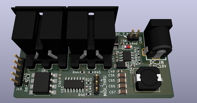
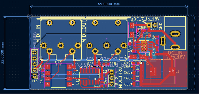
J11 is the 5-pin header to the far right on the core board. On the render it is called J14 but references have changed since. it is there because I made a MIDI+power board that was supposed to be attached to the side similar to the Axoloti but I don't like the layout so far. I might add pads for MIDI in&out circuits to the bottom of the core board so one could solder them on if inclined, and/or try to squeeze the 5V buck regulator circuit onto the top side of the core board, but then regulator noise might become an issue.

In short, it is probably still a good idea to have 5V and MIDI etc. on a daughter board "engulfing" the core.

The power board follows Axoloti's power and MIDI schematics. On the left you can see J15 which corresponds to the 5-pin header on the core board and if they were brought together this way the connectors would be all flush together.


#17

Uh! That’s exciting indeed. Looking forward to it!!! Unfortunately i have no competence in helping you in developing. But if it comes to a kind of crowdfunding, i‘m definitely in. I put so much time into my Axoloti Pedal (Guitar) and unfortunately just bought one. So i really do need a backup. Thanks for putting this project to the future!!!


#18

Sebastian, I strongly encourage you to persevere in your project, we need it and you can count on me as a buyer for a bunch of it!


#19

Thanks all for the support!

  • Well the board is finished and working as described above and I am just letting it sink in (if any caveats or limitations might appear with the current design).

  • Also still trying to find a way to get in touch with Johannes since I don't want to take his brainchild and publish anything without his knowledge and consent.

  • Meanwhile any Axoloti patches are being tested and so far everything works 100%. I have been going through the factory library example and demo patches as well as community demo patches. So amazing what is in there I wasn't previously aware of!

  • It may take some time to test the more specialized objects that require actual circuits connected like serial, SPI, I2C because I'll have to breadboard them up first I guess.

All required object changes have been made and only include the following:

  • gpio/in/analog: remove PC0, PC2, PC3 from the list, add PF6, PF7, PF8, PF9 to the list, reorder pin indexes.

  • gpio/in/digital, gpio/out/digital: remove PC0, PC2, PC3 from the list, add, well, lots of new digital GPIO pins to the list.

  • Then the second revision prototype will have to be ordered.


#20

cool! did you test the usb host functionality already?