Multiplexing 2 shapes with z-axis blanking with Axoloti on Leader LBO-51MA X-Y-Z Display Module Monitor.
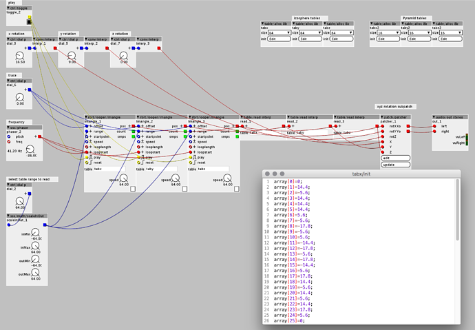
The first shape is a 3d icosphere with x y z rotation, trace effect and LFO. The patch reads 3 tables containing the x y z data of the vertices of the 3d model. The second shape is a mix of 4 sine waves with 90° phase shift.
The blanking is made with analog out.
Multiplexing shapes on oscilloscope
This is very inspiring work. I found it on YouTube last night.
I've been trying to imagine ways to generate 3D geometry in the Axolti ala Oscistudio and here it is in all its glory!
Thanks for sharing your patch from Paradiso last year. I would greatly appreciate a peek at how you manage the tables of the XYZ data in this one.
This is the basic 3d patch. The subpatch for the x y z rotation is from the demo patch "oscilloscope x y cymatics".
I am really curious bout how you get that super quality you got in the videos? I have seen soooo many of these videos over the years, but yours... The quality stand out to what else I have seen. Could you say a little bit about this?
Amaizing..
This could be a way for the deaf to experience the complexities of sound ??? !!!
Or even create sound through image... !!!
+1
Also how would you manage "non continuous" shapes? For example, a cube has 8 vertices and 12 edges. It's not possible from a geometrical perspective to draw a single continuous curve that fits all vertices and edges, you must overlap somewhere.. Could you share some insight on this?
I guess if you move the point fast enough, and set the refresh-rate low enough on the oscilloscope, you can leave areas undrawn. Mere speculation though.
a|x
thank you guys
@jaffasplaffa If you mean the quality of the recording... I use a Panasonic GH4 in 4K, full manual, in a dark environment, a little bit of sharpening in post and export in h264.
@Sputnki For a non continuous scape some lines are drawn twice. A more complex solution would be to blank the z-axis (brightness control) when you draw the duplicated edge. The hard thing with these 3D shapes is to find out the right drawing order of the vertices.
Here's my little secret... make your shape in Blender > connect Oscistudio > have a look into Oscistudio project file.
An oscilloscope does not have a separate refresh rate. You're probably thinking of raster images that are drawn from a frame buffer as a series of horizontal lines. An oscilloscope is vector based, so the rate that the point moves is the same as the refresh rate - or at least it affects the refresh rate directly. The more points and lines that you have (the more drawing), the lower the refresh rate.
One trick is to disable the cathode ray (blank the z-axis) before stopping the motion of the line tracing. On systems that do the reverse - stop the motion before blanking the trace - you see a bright dot at the vertex of each line because the ray lingers longer at that point and creates more brightness.
Raster images are always blank anywhere that you don't actively draw. In addition, even when you do draw on part of the tube, the phosphor only holds the image for a brief time until it decays and is dark again. So, having blank sections of the screen are easy: just don't draw there.
From my blog you can download the basic 3d rotation patch an there is also a link to a spreadsheet to convert the OsciStudio files.


