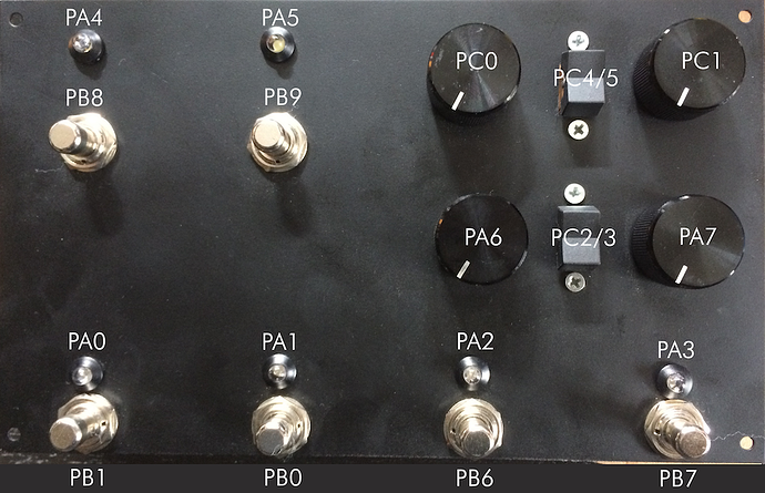
Misusing audio in / out for an expression pedal


#1

Hi there!

Weeks ago I built my Axoloti in an universal enclosure for use it in several different situations. As synth, guitar fx, midi controller, etc.
See the picture attached.

Today I was in need to use an expression pedal, but since every gpio pin is soldered and occupied, I was thinking about misusing the audio in / out in some way.
I tried sending different waveforms out of the audio out through the pedal back into audio in and then try to convert it in k-rate signals to produce any usable data for midi cc. Of course I failed :wink:

I have no idea how to solve this in the Axoloti patcher (except desolder anything to solder on a TRS jack)
Does someone have an idea?

Thanks for reading!


#2

Nice panel!
I'd not recommend using audio input for an expression pedal.
It looks like you're using 2 digital inputs each for the two 3-position rocker switches, right?
With a few resistors you could get different voltage levels from your rocker switches, so you only need a single analog gpio input for each rocker switch, that frees up 2 gpio's for expession pedals.


#3

Thanks @johannes!
I wanted to have the all-in-one-solution for every possible situation. It can be used as foot-controller or desktop synth/fx whatsoever.
New picture attached. Helped a lot in spontaneous situations (Them: "A 24dB filter, some external cc assignments and a clock thru would be nice." Me: "Say no more") :slight_smile:

The idea with the resistor is great. So doing this for both of the 3-position switches means I could save 2 gpios.
But: I always used the "gpio/in/digital" which just gives me an on or off signal out, but no possibility to "measure"? Could you give me a tip?
And since PC5 isn't shown in the list of the "gpio/in/analog", I need to use the "gpio/in/digital".

Or should I rearrange the soldering of the switches?
What do you think?


#4

Yes, you probably need to move some connections around, not all gpio's can do analog input.


#5

Yeah, think so too. Warming up the soldering iron.
Thanks for help!


#6

Another thing you can do to save pins is connect multiple digital switches to one analogue input, you use resisters between them so it acts like a pot, I connected up Eight footswitches with no issues at all, could easily do more, all you need to do is map the individual analogue in values as triggers.


#7

Hey @Gavin
What do you mean with "digital switch"? Do you have an example picture for me?
If I understand it correctly, it's the same way Johannes suggested but with more switches and resistors connected to one analogue input, right?


#8

Apart from the expression pedal, it is exactly what @Johannes describes.
Its basically this schematic shown in the "Official pin in out" post.
Except rather than using a rotary switch, you replace them with individual switches.
The down side is you cannot press more than one switch at a time.
And you can also apply the same to the rocker switches but they should have their own analogue input.
I'm just quite sure about your needs for an expression pedal.


#9

I'm concerned I may have not steered you correctly here.
I'll try and break it down a little better.
Based on your image, appears you have 6 footswitches and 2 rocker switches.
If the all the footswitches are momentary, these can all be connected to one analogue input, both rocker switches will be to an analogue input each. In total using only 3 analogue inputs.
To connect the rocker switches, you use exactly the same as the schematic above, but with only 2 switch option, if you have momentary switches, you can apply as many as you want in same schematic for each individual switch. This is what I did, I chose momentary foot switches because you can always use an object to make it toggle.


#10

If you dbl the resistance could you not work out which combination of switches had been used? Just a thought as I am waking up so could be thinking about it all wrong.