
I don't know much about electronics (so dont take advice), but as far I know it is fine use the minijack out as a line-out. Many speakers have a build in amp (including computer speakers) and also use line level in, so simply saying 'don't connect to speakers' might be inaccurate.
Connecting speakers directly could cause damage, but it would be stupid to do that anyway. just dont use low-impedance equipment (such as speakers)
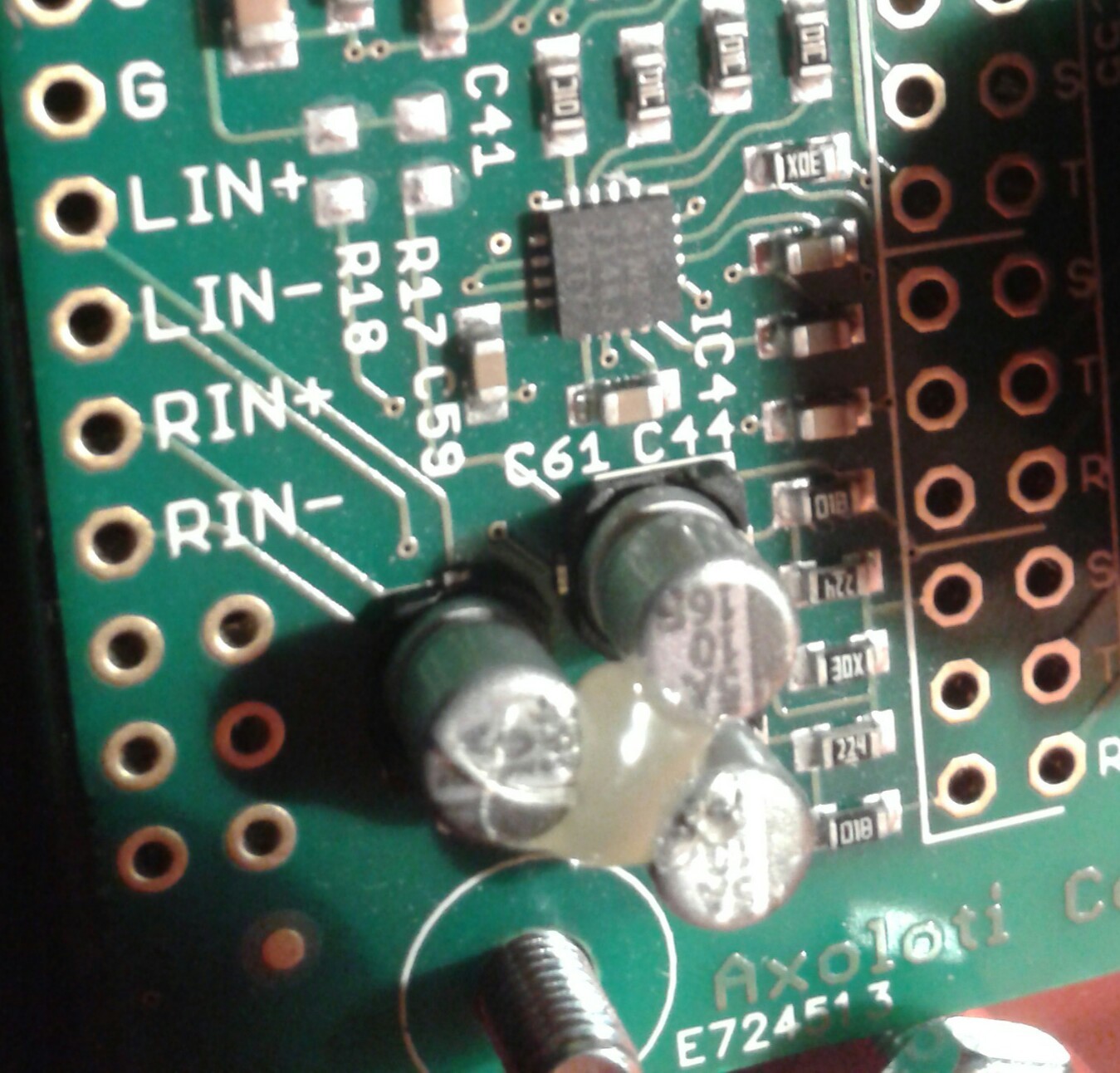
Might have fried the output of Axo
alex
#5
kausto
#6
According to @johannes himself:
The headphone output is biased at 1.65V. That means its ground connection is not at ground. Connecting headphone out to other gear will short circuit this bias, result in U3 (the audio ADC/DAC) getting hot, and probably strongly degraded output quality. It does not damage the ADC/DAC chip as far as I have seen.
You have to use a Di-box with ground lift option to get normal levels etc. Since i damaged my Axoloti's audio out driver (IC4) already  i use headphone out with this one
Sounds nice.
Johannes also said capacitor mod implemented to headphones out is possible.
johannes
#7
That's right, there is only one stereo pair of ADC/DAC.
Yes, analog in can be mixed into the output without passing through ADC/DAC. Could be used for true zero-latency monitoring, dry/wet mixing, or analog bypass.
MONOOUT is used to generate the capless headphones virtual ground.
Using the minijack as line out is fine ONLY if the device connected has its own (isolated) power supply, and is not connected to the computer directly or indirectly.
So, connecting powered speakers is fine, but not if they're powered from USB or have another input connected to a pc soundcard or pc line-out.
Direct analogue path?
mackemint
#8
Thanks for all your replies!
I'll be connecting my Axo to the line input of my Korg KM402, the Axoloti will probably be powered from the computer or a USB battery pack.
The mixer is connected to the computer from my Firewire soundcard.
Ok so I'll check out a cap modification to get rid of the DC bias then..
mackemint
#9
Hello!
Did some quick measurements with my Caltec multimeter since I was a little bit confused about the whole DC offset on the headphone output subject..
These are the values I produced from measuring first on the headphone output, then on the big TRS output, first with no signal, then with a sinus tone of approx. 4kHz from the axoloti. The tone is straight from the oscillator without any processing.
(quiet)
Right headphone output: 9mV AC, -0.1mV DC
Left headphone output: 7mV AC, 0.3mV DC
Test tone:
RCH: 296mV AC, 0.5mV DC
LCH: 295mV AC, 1 mV DC
Big TRS output:
(quiet)
Right (Ring) output: -22mV AC, 7mV DC ?!
Left (Tip) output: 645 mV AC 7mV DC
Test tone:
RCH: -21mV AC, 7mV DC
LCH: 300mV AC, 292mV DC <- double checked this, the DC component seems to be linearly proportionate to the frequency (lower when frequency is lower and up to 600mV at higher frequencies).
Another thing, a headphone amp is supposed to drive a relatively low-impedance load (mine are approx. 85 ohms), and the line input of my mixer is in the order of 10k, so I don't see why it would be bad for the headphone output to be connected to the line input..
I totally would get it if there was a case of a 1.65V DC bias tho..
johannes
#11
That's probably measured using headphone "ground" as reference which is not ground but has a 1.65V DC bias towards general ground.
This topology was chosen to achieve high quality (capacitor-less) headphone output.
Why the DC bias on headphone out?
mackemint
#12
facepalm Yes.
Note to self, don't try to do smart stuff in the middle of the night when you should be sleeping.. Yet again.
OK I'll start a new topic on capacitive decoupling for all the main output-burners out here! ^_^
ndlopes
#13
Definitely something similar happened to my axo core. Very weak output with a lot of noise.
Right output is almost dead, left output has more signal but also more noise.
Axo was connected to an amp that was suddenly disconnected and reconnected,
in that moment a burst occurred and the main output was gone...
However, the headphone output seems to be working without noise.
Summarizing I'm very very sad..and since I got a bit lost in the electronics in this thread,
So what is the cheapest and safer way to use the headphone output as a line out?
Help, please.
keyman
#14
3.5mm (1/8") mini-jack is a headphone output. Use only for headphones (headphone jack is electrically biased at 1.65V.)
johannes
#15
So apparently IC4 (the line output driver) broke down due to a voltage spike. This causes IC3 (just behind the line out socket) to overheat (be careful not to burn your finger when you check this!), dropping the analog supply voltage and then the audio chip would not function anymore (but that seems not to be the case on your board).
This mod would remove power to IC4 and remove the DC bias from the headphone out and couple that into the line out socket:
step 1 : cut the power to IC4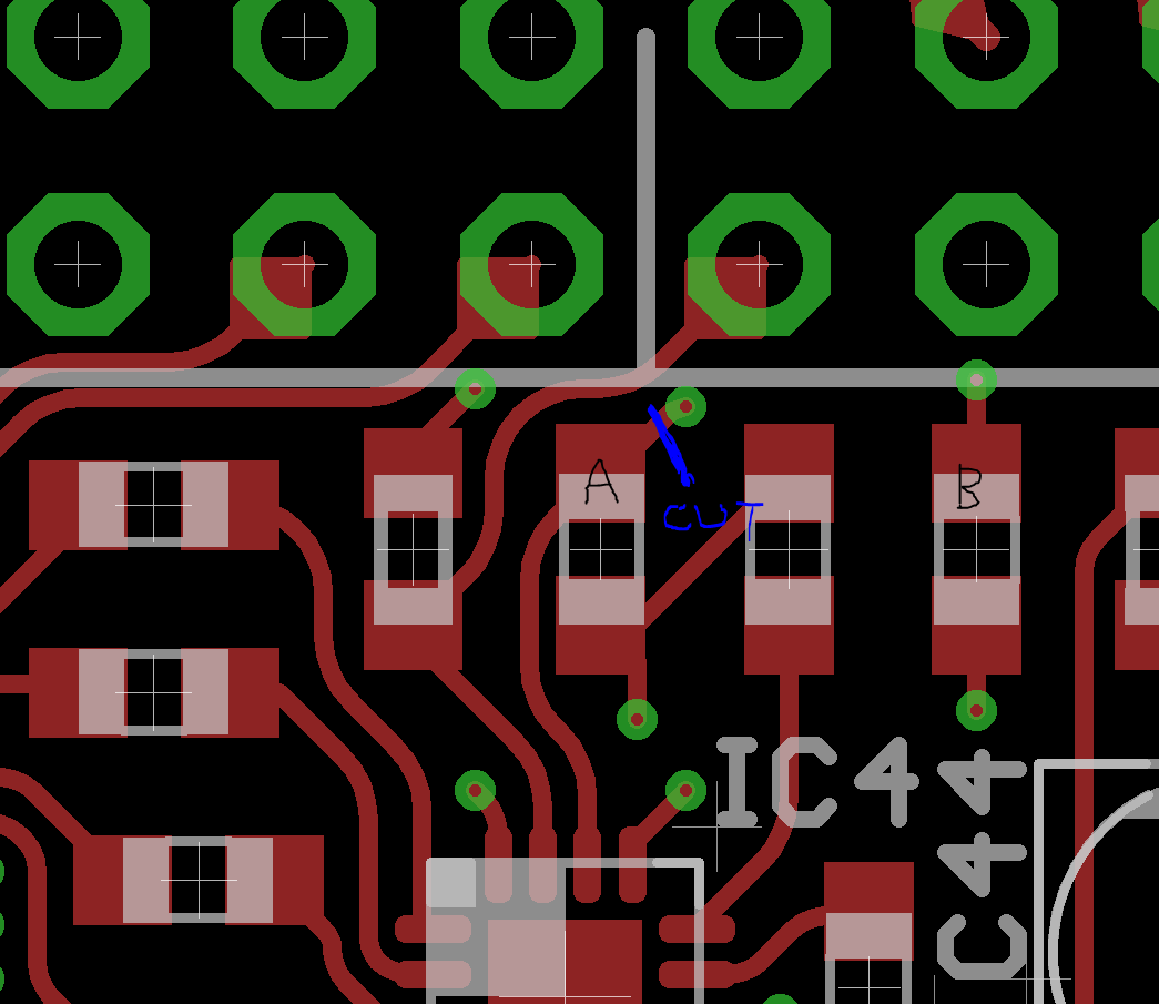
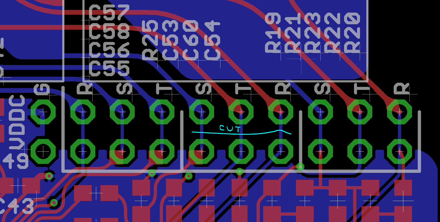
step 2 : cut three tracks on the bottom side.
(blue are copper tracks on the bottom side, red are copper tracks on the top side)
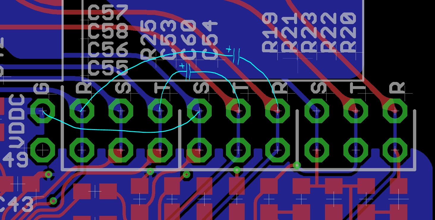
step 3 : connect one wire and two capacitors:
For the capacitors I'd suggest 10 microfarad, 16V electrolytic types. More voltage rating does not hurt. 22uF or 47uF would also be good values, it only makes a difference for low-impedance loads.
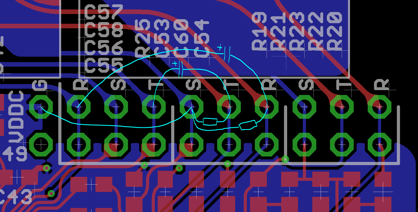
step 4 : add two resistors to bias the capacitors properly
I suggest 10kiloOhm resistors, but anything between 2.2kOhm to 22kOhm would do the job fine.
This mod bypasses the ground loop break circuit. Ground loop noises are most likely when you power Axoloti Core by USB from the same PC that is also involved in the audio path somehow (like soundcard to the same mixerdesk...).
BTW: the 'S', 'T' and 'R' markings mean sleeve, tip and ring. The top row goes straight to the headphone, line-out and line-in jacks, the bottom row connects to the circuitry. This is to allow circuit hacks, like re-purposing the 1/4" jacks to footswitch or footpedal inputs, breaking out to dual mono jack inputs and outputs, or adding a relais for true bypass...
Control transfer failed: -7 - need a little bit of help
mackemint
#16
Hey bro,sorry for your loss. Till be using one of these:
Its cheap and will do the trick.
I tried out a few capacitor based configurations but without satisfying results.
Good luck!

ndlopes
#19
The hack proposed by @johannes.
Used 10k resistors and 1mF 35v Caps.
After all I have a big electronics store in my neighborhood.
Now I've a bit of digital noise (probably due to the USB connection) and it seems that the output is a bit lower...
But completely useful and stable. 
mackemint
#20
Hey @johannes, how'bout if one is feeling friskey and would like to attempt replacing the headphone amp IC? It seems this component (TPA6132A2) is available from a retailer near me..
johannes
#21
QFNs can be tricky. With a hot air soldering station and flux, this can work. Avoid a lot of solder on the center pad - if there is too much there, the component will float on the center pad, not making connections to the signal pads.
kausto
#22
I guess somewhere (on site/on forum in form of conspicuous sticky topic) should be a recommendation how to avoid this since it can happen easily.
mackemint
#23
I guess I'll have to see a friend about a hot air soldering gun then...
Before I do something possibly stupid,I guess its the QFNL IC in the image? It says IC4 but has the text "AIWI48JPDTY", which doesn't turn up any results when I octopart it..
harryt
#25
Hi Johannes,
I just got around to experimenting with my v1.1 Axoloti today. I love it! But it just broke. It seems to be behaving like others have described in this thread - low voltages and IC3 heating up.
Should I follow the procedure to bypass IC4?
Many thanks,
Harry