Mapping pot curve to linear


#1

Hello,

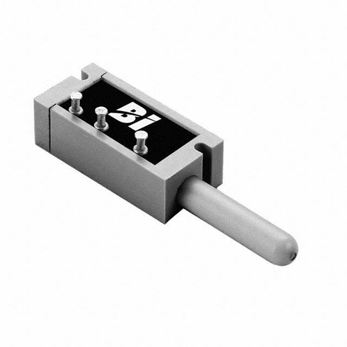
I have a button-like pot on PB1 working well. Measuring its input with positive k rate signal display (dial p) I get 0 to 64 aprox. But the first milimeters of the pot already output 53, with the rest of the button going from 53 to 64... a very very steep curve.

I need to turn this into a very linear curve so the difference between how much i push the button-pot translates linearly into the value I get in the patch.

What object(s) can I use to do so?

Thank you very much in advance.


#2

what is a buttonlike pot? can you post a link or an image?

a lookup table solution comes to my mind, what resolution do you need in the end? 7-bit midi?


#3

I am talking about this: https://www.digikey.com/product-detail/en/tt-electronics-bi/404R10KL1.0/987-1025-ND/2408603

You press the tiny rod , but it is not on/off, but pot-like... continuous.

The value will go into a math multiplier object to act as a volume regulator of the output of a filter.

I may have already accomplished what I was looking for, by using an exponent function object (exp.axo) after the gpio object, now I am getting 0 to 64 along the rod, linearly.

Can I use that on the multiplier object to control volume? I am still a bit lost with colors in Axoloti. Need to read well the info.

Thank you!


#4

i would use a vca object for volume


#5

Ok, may I know why ?

And, regarding my original question on the linearization of the input, did I use the right object?

Thanks


#6

if it works, then an exp object is perfect, sure. by looking at the code of the vca object you can see that it interpolates the blue signal over the 16 times faster red signal, so the volume changes will be smoother then with a multiplication object where it just uses 16 times the same signal to calculate the gain.

generally red cables are calculated 16 times the speed of control rate (all other cable colors).

control rate: 3000 times a second
samplerate: 16x3000 = 48000 which equals of course axolotis samplerate


#7

I’m wondering why you’re getting such non-linear behavior from a linear pot. (The part number you linked is for a linear device. And expensive.)

I’d carefully test that pot with a multimeter and a ruler, to see what it’s actually doing.


#8

I agree with @tele_player, if it's a linear device it should give a linear response. I'm wondering if it is properly connected. Similar to what @tele_player says, you can measure the output from the pot with a multimeter when it's connected, and see if the resulting output voltages represent a linear response.


#9

Actually, I would recommend testing it out of circuit, measuring resistance with ohmmeter.


#10

Ok I hear you both, thanks.

Before I do that, just to be sure, the objects I am using are 'gpio/in/analog' (PB1) and 'disp/dial p', is that correct?

Thank you


#11

Yes, those objects are correct, if that is where you connected the pot.

Note: the pins are numbered 1-3-2 counting from the pushbutton. Pins 1 and 3 go to 3.3 and ground, pin 2 goes to analog input.


#12

these pushbutton pots sure look nice.. gonna see if i find something with bigger moving range? might make some interesting control input devices.


#13

They’re crazy expensive, and I tried searching for similar/cheaper, with no luck.


#14

yeah 20/30$ is lower limit huh? i might give it a shot at some point, for like a standout feature. i see a down-pushable spring-action handrest underneath the pitchbend/modwheel combo on the side of a keyboard.


#15

Actually you were right.

I was not connecting those pins in the correct order, I guess I got confused by them not being in order in the pot itself.

Thank you for your help.