How to use the gpio objects?


#1

Hi,
I am new in this community and there is so much to learn at once !
I have done my first patch that I want to become an autonomous little synth, in a box with pots.
But I cannot understand how to use the gpio objects.
I have read the great book of Jan Vantomme and the explanations on how to use these objects are not sufficient to me. He gives an example for testing pots. But how to do with objects related with other objects and not loosing the link with these objects ?
I upload the patch I have done and I want to associate the blue pots in my patch with physical pots on my box.
Can someone explain to me what I have to do with the gpio objects ?
Best regards,

PhilWAVES.axp (5.7 KB)


#2

Check out this post https://sebiik.github.io/community.axoloti.com.backup/t/how-to-add-knobs-to-axoloti-board-not-in-patcher/503 , Cheers :slight_smile:


#3

Hi,

probably I was not clear enough in my question.
But the problem to me is the use of the gpio objects in the patch itself.

Cheers

Phil


#4

Sorry the use of GPIO objects in "real" patches isn't clear from the book. I'll tackle that one in the next revision of the book.

Here's a quick exlplanation:

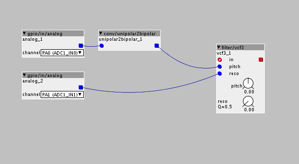
The gpio/in/analog objects will give you a signal from 0 to 64. If you want to use this signal to control values between -64 and 64, you need to convert the signal with a conv/unipolar2bipolar object.

So if we take a look at the filter/vcf3 object, you'll notice that there are two blue inlets, one for the pitch and one for the resonance of the filter. The pitch dial goes from -64 to 64, so you'll need to convert the incoming signal. The dial for the resonance is 0 to 64, so there's no need for conversion. If you leave the dials at their default position, you can control the full filter with the potentiometers.

Some inlets/outlets on objects will also feature a + or ± sign to show more clearly what signal is expected.

Hope this helps you.


#5

In your patch you can use something like this:


#6

Hi ndlopes & janvantomme,

thanks for your quick responses. That's a community !!!
I think both your explications have helped me a lot.
I have completed my patch with respect to your advices and I hope it will functionate "in the real life".
But I have a question again.
If I would intent to use physical pots to adjust the "a, d and r " parameters of the "env/adsr" object with no inlets, how should I do ?
Would it not be possible to affect such a possibility to the dial directly, in the object ?
Thank you again.

PhilWAVES GPIO.axp (10.1 KB)


#7

It is possible to connect pots to a modulation source or MIDI CC and use that to control the dials, but I wouldn't recommend it. It's best to use the ADSR with inlets, and use the same technique as I explained with the filter.


#8

apologize for asking this here but I cannot find any similar topic related to this, and this question might help someone in the future

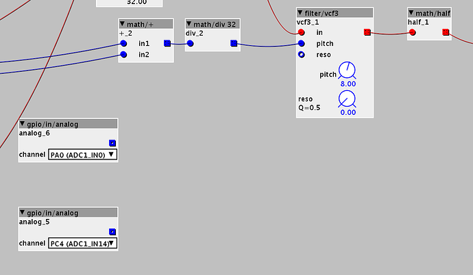
consider for example the following object, the filter/vcf3
has a cord from the math/div32 connected to pitch
I also want to control the pitch dial with gpio... how can I do this?

already tried with internal CC but the DSP load goes to 100%


#9

Best is to let the pitch and reso dials at their original values.
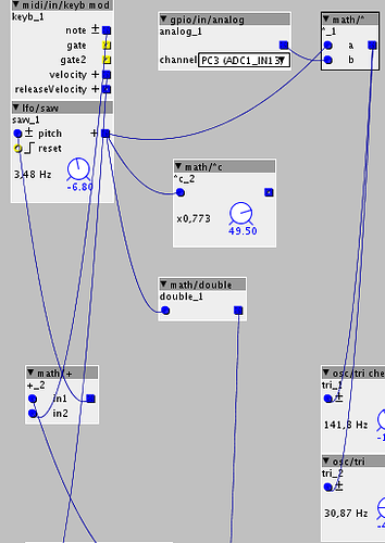
You can use the math/+ object to add the value of the gpio to the math/div signal.
Or use the **math/*** value to use the gpio signal as an attenuator.


#10

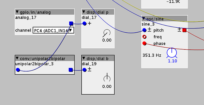
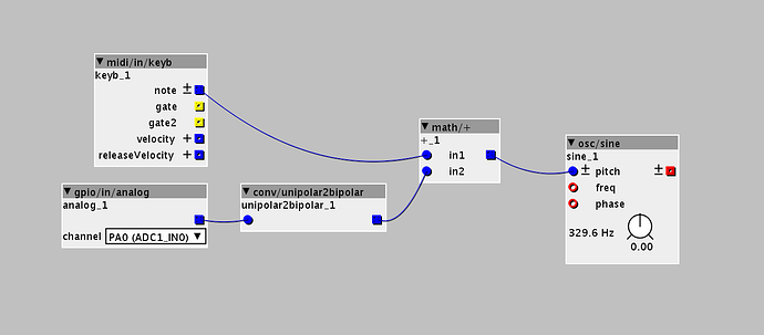
@janvantomme thanks, I understand now that I can use 'math' objects to overlay and mix incoming data.. could you be so kind and tell me how to control this osc/sine dial with an external potentiometer?


#11

The only way to control the dials is with internal midi or mod sources as mentioned earlier in this topic.

Best way is to convert the incoming signal from the potentiometer to a bipolar signal, and add that to the signal of the midi keyboard note. This way, you can subtract or add values from the note value. Potentiometer at 12 o'clock will leave the note unchanged.


#12

makes total sense! thanks so much!