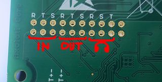
Hi friend, I didn't found any info about it.
I'm confused because on the board, for both audio input and output, there are R+ and R- and same for Left. I'm working on a PCB with stereo jack socket from Thonk (green thonkiconn) for output and input but I don't know which Right and Left I have to choose.
+ ?
- ?
both ?
Thanks 
How to solder pin for audio input/output to stereo jack socket?
s8jfou
#1
Blindsmyth
#2
The pins labelled rts (input) rts (output) rst (headphones) are where you have to go.
r = ring = right
t = tip = left
s = sleeve = ground
s8jfou
#3
Well, thanks a lot for this info, just to be sure, is that right ?

So there are two in, two out, and two phones ? (3 in addition to these already soldered to the board)
Also, Do I need to program anything in the patcher to get sounds ? or just soldering and that's it ?
Many thanks for this quick answer mr @Blindsmyth
Blindsmyth
#4
Yes that is correct! normally there the 2 pins are just doubled. You can however cut the connection between the two.
Then one row will connect to the jacks. The other row will connect to the ins and outs of the board. Like this you can repurpose the onboard jacks for other use.
