[help] Driving a pot (and pwm dac)


#1

I'm trying to mod a monotron Duo so I can sequence it from Axoloti (and generally just midi→cv the thing.) So far I've got control of the keyboard and the cutoff, but in order to be really useful, I at least need to be able to manipulate the pitch control since the keyboard is a single octave.

The device runs on 2xAA (I'm powering from the Axoloti to prevent accidents) and runs the logic on 3.36v. Keyboard and cutoff are conveniently on the 3.36v rail, but the pitch knob is on a 5v rail, VCC here:
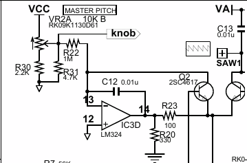
Schematic at the bottom of: https://www.korg.com/us/products/dj/monotron/page_3.php ("DUO") Nb. the "pitch" label is a computer controlled thing, not visibly exposed, and probably not something I would have any luck messing with. "Knob" is the input.

Perhaps this was doomed to fail, but I put a PN2222 across vcc and the wiper leg of the pot, with one of the PA dac outputs on the base. I do get some range out of it, but not nearly the full range. Reducing the base resistor had little effect, but the Duo did start misbehaving a little. Like the voice gate was left open. I couldn't tell you if that's a charged up capacitor somewhere, a really confused MCU, or both. (The "knob" label goes off to the MCU.)

So am I taking the right approach and just missing something, or is this doomed to fail? I am not experienced in building this kind of thing, and "soldering transistors to pots" isn't in the 101 material.

I'm also going to need to do the pwm dac thing and the only reason I bring it up is I'll be looking to use it on this pot (and others.) I'm fairly confident the filter itself is going to behave, I just want to mention it in case there might be some interaction that I should account for in the final design. I don't expect interaction, but at the end of the day idk what I'm doing.


#2

I am not familiar with the monotron or how pitch vc is realized with it but are you sure you need a pwm DAC for it? The axo has two configurable 12bit DAC outputs and a convenient object to go with them.


#3

Normally you'd be right, but I'll be using those outputs for other things. It might make sense to shuffle things around, but in the end I have a few pots I'd like to do this with (in the same patch) so at least one will need the pwm dac treatment. For the moment I am using one of the regular dac outputs to experiment.


#4

Around 10 years ago I had a plan to use arduino and a bunch of high precision DAC to control Monotron DUO (before I successfully modified other two monotrons this way easily). Then I started reverse engineering DUO model and realized how much work it needs then gave up.

I assume that there is no easy way (without heavy modifications of original circuit).
Here is some moments I remember. (Disclaimer. I'm not an engineer, just hobbyist)

First, the gate control. There is a risk. Lets assume that the pin IC2 P1.3 when there is no gate this pin is in open drain mode (otherwise it could be in hi-z mode which is basically floating pin which might bring false triggering), which means that if you try to supply voltage directly to the pin (or testing point) and voltage source is capable of producing more than 20 mA current you can burn the MCU (or particular pin). Need to double check this before using 'raw' external gate.

Second. Pitch. Oh, honestly I don't understand schematic completely (because i'm zero in understanding transistors). But the master pitch control is a voltage divider/mixer with inverting amplifier, it is supposed to produce some offset (like octave switch but smooth), this is very clear. Then signal from MCU TA0.1 which is only provides one octave range shift signal (either provides PWM or real DAC don't remember, need to check data sheet of MSP430G2231). Anyway it also somehow processed with IC3B adding offset and gain and then finally mixes together. If I remember correctly I checked voltage at the joint between Q1 and Q2 under different conditions (like position of master pitch and ribbon stripe) and found out that voltage changes there are extremely little. Which makes me think that VCO are controlled with current not a voltage.
Possible solution would be to unsolder Q2 and R23 and then experimenting with some diy made voltage to current converter.


#5

Thanks, I hadn't looked at that. I was looking at getting the MCU to do it's usual job by controlling its inputs, but maybe going a little deeper will work. (Someone somewhere said something about SAW2 being what you needed to patch into, but that looks a little too deep into VCO2 to me.)

As for gate, I haven't been using it. Vrib on A0 (adc10) is getting the MCU to generate the gate, which seems logical from the schematic.I think Vrib is all I need for the keyboard, but I haven't fully mapped it (planning on getting pitch knob working first) so I can't say that definitively.