Guitar buffer and input protection


#1

Hi,

i am currently testing a small buffer for the input to connect a guitar directly to the Axoloti. This way the high impedance from the guitar is converted to a low impedance output. The buffer is power by the 5v output, and is based around a OPA2134 (singe supply rail +5v). The current draw is around 8-10 ma so that's all good.

Now onto my question: Because of the high transients of a guitar, and the way various guitar pedal work, the output voltage (AC) can vary quite a bit. Th ADC input is run at 3.3v, and i cannot seem to find if there is build in overvoltage protection, or that i should add this myself. And if i need to add this myself, what is the bast way of doing this, connections and component wise.

Best regards,
Kriz


#2

I think that the abs maximum voltage of the buffer cannot exceed half the power supply, 2.5 V, it seems that the AD clips at 1 volt rms so a voltage divider is needed. If it works well, can you share the schematic?


#3

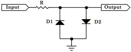
A simple diode limiter circuit might work well here. I can't give you any specific value suggestions because I don't know what Peak-Peak voltage range the audio input can handle (3.3V makes sense but patatos's post suggest that may not be the case)

Different diode types (silicon, germanium, schottky, coloured LEDs) all have different forward voltage characteristics, so with a bit of research, you can probably find a suitable selection. Otherwise, a slightly more complicated circuit may be required to specifically tune the limit voltage.


#4

The specs of the ADUA1961 state that the Line input: Full-Scale Input Voltage (0 dB) : 1.0 V rms ( 2.83 V p-p)
Running a OPA2343 (my opamp) from a 5 volt supply gives a max of 4 v p-p.

The problem with a voltage divider is added noise. typically the generates about 200- 400 mv if i'm not mistaken. The main problem is with the high transient spikes.

I'm mainly testing buffers like http://www.generalguitargadgets.com/pdf/ggg_ic2buf_sc.pdf


#5

Your diode network is for a clipping opamp design, distortions, etc. Normally for input protection you use a diode network from the max positive supply rail, and from ground. But i'm not a electronic engineer, so i could as well be wrong


#6

In principle you are right but don't overestimate the thermal noise of the resistors, is in the order of microvolts https://daycounter.com/Calculators/Thermal-Noise-Calculator.phtml


#7

So if I understand correctly, you want to connect your guitar directly to an Axo analog input, hence your need to reduce down to 3.3v peak to peak.. ?
Out of curiosity, why ? can't you just connect to the audio input then use objects to achieve your desire ? It makes little sense to connect to the Axo analog input directly as it can only read in K-rate.
If I have got it all wrong, then interested to know what I have missed .. ! :grin:


#8

Exceeding the maximum input voltage of the ADC can damage it.

Note from Lokki: I am talking about the audio inputs of the Axoloti, not any GPIO pins


#9

you are "cross" talking. @Gavin thinks that you want to use the additional analog inputs (not the audio inputs) for your guitar, which as he pointed out correctly does not make much sense.


#10

The reason for my comment is, the audio inputs on the Axo already have a level of protection, I can understand the desire for a guitar buffer, as I have made a few of these already and work well between effects and the Axo etc, I can share an extremely simple one if you like, it can even easily be split for multiple ouputs. But they all run on 9v.
Although maybe I have missed something in all this, but I don't see the need to protect the audio inputs from a guitar signal unless you are doing something unorthodox.


#11

I looked everywhere to see if it had any input protection, but couldn't find it. That makes it way more simpler to integrate.

@Gavin Thanks for the offer, but i have made a lot of buffers in the past, so i'll manage. But i'll post a schematic here for future reference.