[GPIO I/O] Example 74HC595 shift register & SPI


#1

Hi everyone,
at the moment, I'm trying some ICs with axoloti and want to share my results. It maybe helps someone and we can learn from each other.

Patch Description:
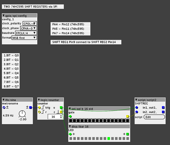
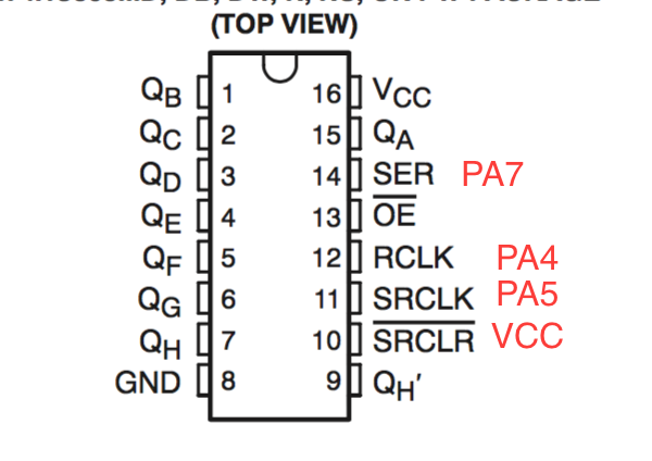
Two shift registers are connected to axoloti's SPI. The single outputs (Q0…Q7) of the 595s are gated by a simple step sequencer. Check the script object for more details.

Download Patch: 74hc595 shiftregister stepseq.axp (4.7 KB)

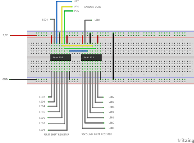
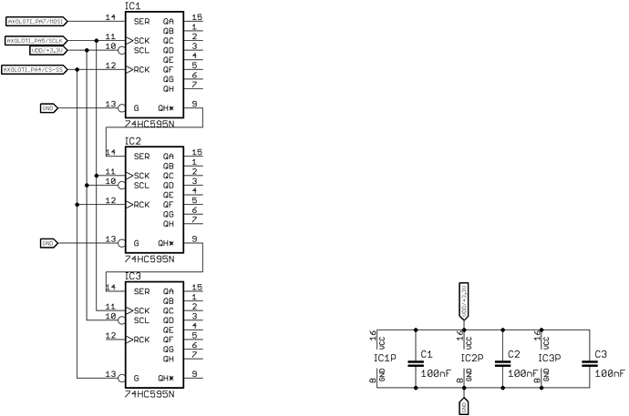
Schematic:


Help needed with 74HC595
Addon Board for extra input / output?
PA5. First time doing SPI. Bad signal?
Hugo Contributions
Djeremaille contributions
#2

Hi Paul
Is it possible to use this circuit as some sort of expander for digital outputs? (more than one led active at once)


#3

hi sputnki,
sure. The 595 Register is a 8bit register. Every bit stands for an output, which you can turn on/off (0/1). So you can turn on/off every output.

Example Script (one 74HC595):

uint8_t *txbuf;

void setup(void){

static uint8_t _txbuf[32] __attribute__ ((section (".sram2")));
txbuf = _txbuf;

}

void loop(void){
spiSelect(&SPID1);
txbuf[0] = 0b10010001; // turns output 1,4 & 8 high, else low
spiSend(&SPID1,1,txbuf);
spiUnselect(&SPID1);
chThdSleepMilliseconds(1);
}

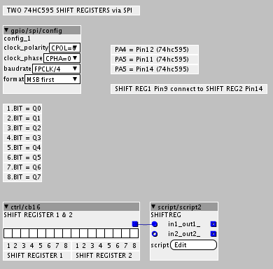
check this patch: 74hc595 shiftregister counter.axp (3.0 KB)

it's a simple cb16 object connected to the SPI out script.


#4

can't load the patch ..
i tried 2 connect myself with the second code ...
the lights burn but no sequence ...

it seems 2 work because i have some strange behavior
with start up and because a patch boots ...
see for yourself !!! lol

https://www.facebook.com/reinhard.roelandts/videos/10208653137591820/?theater


#5

The patch is running now , my mistake !
But i can't find a way, tried a few things
to keep it running in sync with a midi clock
or my leds stops at the end of the cycle or...did not find it yet !

The patch itself i have 2 run different than on the picture
the baudrate i have 2 set fpclk/8
2 have a running led

i would like 2 make a step sequenser with input buttons
maybe thru a led matrix , but as a noob any suggestions are welcome


#6

Hello!

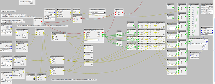
How can I drive leds on a 74hc595 with som trigers inputs?

As you can see I have a lot of leds to drive (15 at the moment ) but I don't know how to send the correct values to work with the 74HC595.


#7

I think, there two easy option:
1. copy and edit the script2 object code and 595 code to a new obj with more inlets.
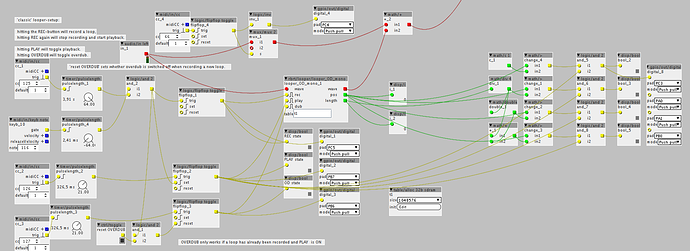
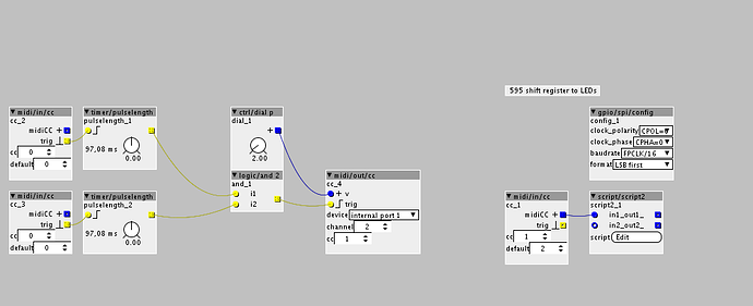
2. internal midi cc value to LED. e.g. if CC#1 == 2 then trigger LED 2 , else if CC#1 == 3 trigger LED 3 etc. like on the pic:

hope this helps a bit


#8

Thanks a lot even if I already found another way to do it.

With a script from @thetechnobear (oneliner_ik) that can convert integer into fractional:


#9

Hello @paul !

Again a noob question:

Can I control more than 2 74HC595 ?
I have tried by simply wiring 1 more and using your script but It don't work (it's made for two).
I don't know nothing in C coding and I don't understand your script.
It would be nice to have a commented version of it as I don't have time to learn C for the moment.


#10

Ok, I modified the script without understanding what I do and it's working but I have a problem:

The three last leds (22, 23 and 24) are not working.

I am driving this with integers converted to frac. The integer for Led 22 is 2097152. Led 23 is 4194304 and 24 is 8388608.

Maybe the addition of all these numbers is too long...


#11

hi @Djeremaille

yes you can easily connect 74xx595 Ic to one long daisy chain. It's the same as shown in picture above.

Connect the first 595 Pin 14 to Axoloti PA7(MOSI) and each 595 Pin 9 (QH*) to the following 595 Pin 14 (Serial in).

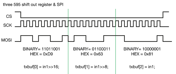
Each output of 595 IC is controlled by one bit and it needs 1byte [8bits (8 states of 1 or 0)] send at each rising edge (0/1) of clock. check spi modes at wikipedia for further spi setup.


to control three 595 you need to send a byte chain of 3 bytes. MOSI of axoloti sends 1byte at a time. Each 595 starts to receive MOSI messages when CS is switching from 1 (HIGH/3,3V) to 0 (LOW/GND) and it's pushing the incoming bytes to its QH* pin till CS is 1 (HIGH) again.
the first send byte should always be received by the last 595 IC in the spi chain.

Hope this makes it a bit more clearly. To learn more about 595 and SPI you can have look at many arduino and raspberry pi tutorials at youtube, adafruit etc…the principle is the same but pinouts are different :wink:

Axoloti patch for three 595.
three 74hc595.axp (2.3 KB)


#12

Thanks a lot!

So my script was correctly modified!

Maybe I have to add capacitors.


#13

I haven't worked with frac format. I always try to work with binary or hex formats. this site is very usefully to have a look at bit codes: http://www.binaryhexconverter.com/

here is a short overview how the values should be to turn on or off LED 22:

EDIT: and an other converter site which translate binary to frac format and back: http://www.exploringbinary.com/binary-converter/


#14

Thanks for you help!

All is working perfectly! In fact my third shift register was improperly plugged .....


#15

Hi I'm interested in using 2 74HC595 for driving my leds too, the instructions here look prettly clean, thx for that!

I have two questions.
When I look for parts I see several 74HC595 but each with a different letter at the end. now I got 74HC595N is that allright?

And could I also use this in order to multiplex several digital inputs like buttons?


#16

The short answer: take the N suffix.
The long answer: suffixes often indicate package type and temperature range. The true reference for the meaning of suffixes is the manufacturer's datasheet. 74HC595 is a generic part produced by several manufacturers, every manufacturer has its own conventions with some overlap.

I believe 74HC165 could be used for digital inputs, similar to 74HC595, but have not tried.


#17

or a cd4021, I believe they are mostly the same


#18

Hello!

There is two objects under /gpio/spi that could help you:

/74HC595inputsX4 with a help patch

/shiftregiter to replace the script from @paul


#19

ok thx, good that I picked the one with the N suffix :wink:

Is there anyone here that has tried this?

@Djeremaille
Thx I already saw them and planned to use your objects :slight_smile:


#20

Hi I'm trying this out with no luck here.

I have soldered the connections according to the desctiptions here with 1 shift register and one led to try this out. Is this correct?
?

Would it be a problem to use the same Vdd for switches too?