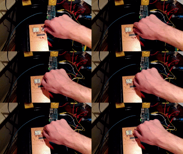
Hello everyone,
I've been playing with my axoloti and imagining some potential hardware designs for it, and I picked up a few components to use in a mono-synth box I want to build. I have a rotary encoder and 2-digit seven-segment display that I'd like to use for patch or parameter changes, and I picked up a an MCP23S17 16-bit digital IO expander (datasheet here) so as not to use up 14 pins for the display alone. So I've been trying for two days now and still can't get any output from the GPIO pins. 
I should say that I'm a computer programmer by trade but have never really done embedded/serial/chip programming (or much of anything in C) so a lot of my confusion is just my inexperience. I put together a patch and script based on the LKM1638 example patch Johannes recommended, as well as some elements from @paul's 74HC595 shift register patch. I also took the register addresses from this tutorial.
I know that the chip select, SPI clock, and data output/input pins should be PA4, PA5, PA6, and PA7, but their arrangement seems to inconsistent between patches. I've tried several combinations, but is this documented somewhere?
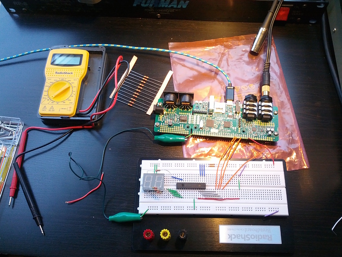
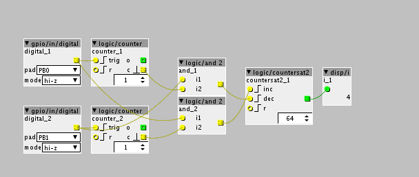
Below is a photo of my breadboard and the patch is also attached. I'm sure there are some obvious mistakes throughout. I can get segments to light up if I connect the "interrupt output" pins (19 or 20) to the display, so it clearly has power, but otherwise no dice. Can someone point me in the right direction?
mcp23s17 io expander.axp (3.1 KB)

