Did I fry my DC part?


#1

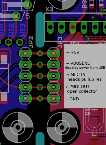
I was just working on an axoloti project. My board was pwoered by 12V fro the dc input. I was trying to measure the 5V pins next the unused holes on the midi side of the board. Because I wasnt getting anything I was measuring the 5V and Ground on the Dc/midi part --> main board pins.

While doing so I accidently touched one of the middle pins with the multimeter and suddenly my board went off and wouldn't turn on anymore.

So I tried to power from usb, that did work. Question is: Did I fry the DC part somehow?


#2

Hello, can you be specific about which you touched? Was it VBUSEND with the probe still touching 5V? Did you solder pins onto JP3 and touch them, because the probe slipping and connecting two pads at once seems difficult to do?

On a positive note, if the rest of the board is fine, any damage is probably quite limited. Can you use the MIDI DINs?


#3

He thx for the reply!

Idk which pins I exactly touched but yes it could have been vbussend and 5v. There is pinheaders soldered but I was measuring from the back.
After this i also checked if the 12v do arrives at the dc plug and I get the 12v so the psu is not the problem.

That is true but without the dc input axoloti becomes practically useless for me because I use sensitive inputs like guitars with electromagnetic pickups and I always have noise from usb controllers and other noise when I power from 5v...

But propably this might be fixable?

Midi in at least is Stil working. I have fried complete boards too in the past so I want to try if I could just reuse their dc part.


#4

Can you power it with just the 12V again and measure the voltage between GND and VBUSEND on JP3.

If it isn't 3.3V, can you remove all power and then measure the resistance between them - it may take a few seconds to settle as there's a capacitor across them.


#5

There is 0V between gnd and vbusend. Resistance is 2.3ohm.

When I power from usb there is also 0v bettween 5v and gnd.


#6

Yes, you've blown D4 which is a 3.3V zener diode. Putting 5V on it without a limiting resistor destroyed it and it's failed short, acting like a low value resistor. Look at page 2 of the schematic:
Axoloti Core v1.2

This has pulled pin 4 on U1 (ENABLE) low which is why there's no power. This also pulls pin 4 of U4 low that enables power using USB (according to the datasheet for this IC, it enables when pulled low.)

If you can get an SMD 3V3 zener diode and know what you're doing, it is an easy fix - the component can be handled with tweezers and a normal soldering iron. You could use a through-hole zener if you have one and bend and cut the leads short. If you want some cheap SMD zeners try eBay or Banggood:
Banggood cheap zener diodes

I reckon there's probably nothing else that's damaged.


#7

Oh wow thanks alot! I have a some through hole 3.3V Zener diodes for protecting gpios here as a matter of fact, but I guess that could become a bit of a messy fix.
I'm not really experienced in smd soldering. The last time I tried hacking an smd delay pedal I screwed it up but maybe I can ask my more techy friends.
I live like 10min from a conrad, so I guess they either have an smd diode or can order it for me.