Cut the board at the wrong place


#1

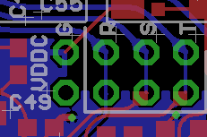
When cutting the connections at the trs in, out and hp out Ive accidently cut too far berween the two insert points labeled "g" (ground?)

Judging from this scheme https://sebiik.github.io/community.axoloti.com.backup/uploads/default/1c1f1b6ee18261ee991bb5f523639865a0641214
I think nothing should be damaged but I recognized irational behaviour from my Outputs so my question is did I screw something up?

#2

can you post a picture of the cut ?


#3

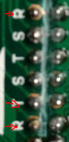
Hey topk 2 pics with my phone, hope you can see it:


ps I just realized that I removed solder bridges without a pump, mybe there is still traces of soldering iron that cause my irratio al behaviour. But ir would still be good to know if I screwed somethinh up with the cut.


#4

OK, can't be entirely sure what setup you were going for with these cuts, but it appears as though the last 4 point sets are all related to the headphone output. I have shown in the picture.

I don't use my headphone bits, so can't comment on potential problems.

Was the weird behaviour you had with using the headphone ?

The other thing you could do to test the damage, is remove all your soldering from all 8 points, and test.


#5

Thx for looking into this! As I said I cut all the audio I O connections, trs in out and headphones in order to repurpose them. I use two axoloti boards that send audio back and forth, and get audio from the same source, so this was much easier to setup with the insert points and then use the Jack for putting out audio of axolot1 on the left and axoloti2 on the right side.
BUT one cut was not intended, the one between the two insert points labeled with "G" that you posted. So that's why I'm asking if this is a problem.

The irrational behaviour involved outputs dropping in and out. BUT I didn't have the possibility to have "neutral" testing condituons. I also had to remove solder bridges without a soldering pump, that might have had an unfluence as well.


#6

Your solder joint do not look good, there appears to be only solder attached to these pins, not to the pads.


I'd suggest to reheat those solder joints with a soldering iron, and make sure the solder flows nicely.
I see no evidence of a cut at the wrong place.


#7

@johannes

Thx, I'm now back home and finally have "neutral" testing conditions again, everything seemed to work fine, but I will redo the solder joints just to make sure.

The "wrong" cut is between the last pair of pins, next to headphone out pins, labbeled "G" on the picture gavin posted. I was wondering if it's a problem that I cut there. Are these another ground connection?


#8

That last pair of pins, labeled "G" and "VDDC" should not be bridged, they're not bridged on the circuit board, cutting there is harmless, but I suspect you're bridging them on the pinheader, which causes a short circuit.


#9

Good that's what I wanted to know :slight_smile: I didn't experience short circuit so I think everyhting should be fine.