Control two-color leds with one pin? Any ways to maximize use of gpios/add more gpios?


#1

Is it easy or even possible to add bi-colored led, so that there is red and green in the same led.
Like this:

And if its possible to use it, is it easy to make it function with patching?
I have patched the default leds so I know a little bit about patching the leds :slight_smile:

Or should I just use normal leds with one color to keep it simple, I am after all not very experienced with soldering and electronics. Im gonna use breadboard for testing.

The rgb leds would be even better to get more feedback information about the changes in the patch. Ive searched for the multicolored leds from this forum but havent found out if its easily doable for me.

#2

Yes, it will be easy. For a two-pin bicolor LED, you need a series resistor (~220 Ohms) like for any normal LED (no matter at which one of the bicolor LED pins). However, you will need two separate digital outputs of Axoloti, to which you simply connect that Resistor/LED combination. That is, from output to output, instead of from output to "ground". One of these outputs = 1 and the other = 0 gives you red, 0 and 1 gives you green. Note that both 0 and 0 as well as 1 and 1 switch it off.
Three-pin bicolor LEDs are different: They need two series resistors, but allow mixed red/green = yellow, too. And four-pin RGB LEDs even more mixtures, appropriately.


#3

Ok, thanks for answering. So I can use the same resistor as I was using a regular one color led?
Im not very experienced in electronic diy things but im a pretty fast learner. That sounds kinda easy.
Im planning to add my axoloti 5-10 potentiometers, 5 buttons, 5-10 bi-colored leds for feedback and ir distance sensor. Is it possible to add those to the standard axoloti? Anything special I should consider?
Thanks in advance for all the help!


#4

Yes, the same resistor.
An additional idea: Yellow should be possible after all if you let it blink red/green by programming a patch that switches between 0 / 1 and 1 / 0 at the fastest possible speed.


#5

Okay that would be pretty cool, I wonder if it could make the led worn out faster when switching constantly with fastest speed?
Any other ideas about my plans?


#6

Don't worry about the continuous fast switching, no problem at all for LEDs.


#7

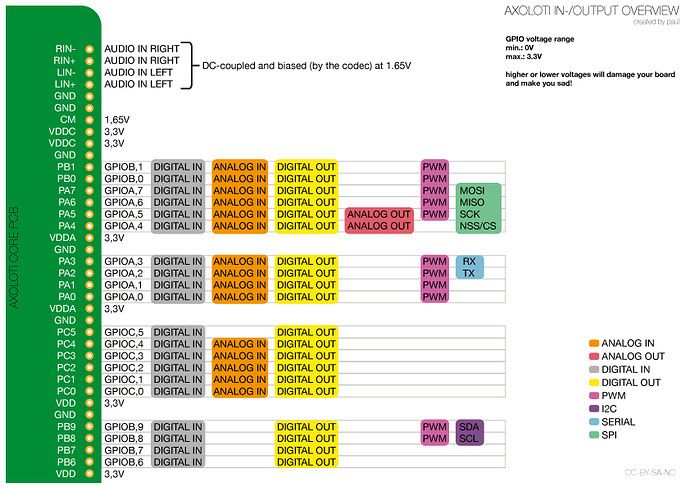
Im trying to understand this picture. Is it so that all the gpios are digital in, analog in and digital out at the same time except the PB9, PB8 PB7 and PB6 which are not analog in.

It seems pretty simple, almost too simple to be true, thats why Im a bit suspicios :confused:

All the GND outputs are the same? Or is there a difference in them? How many potentiometers is it possible to add sametime? And if I want to do a patch where pressing a button lights up a led do I have to connect the led in to the button or can i just connect them to different gpios and make the function in the patcher?

I got many questions :smiley: got alot to learn before my electric parts arrive in mail. I don't surely want to break my device :sweat_smile:


#8

I wonder if those two colored leds are also possible to use in one color also? One pin to ground another to output?


#9

Could it be possible to change the color of abi-colored led with using only one gpio?

I found this but i wish someone more experienced could take a look:

Driving a bicolor LED from a single output pin

Is there a way to connect multiple components to one gpio or get more gpios with somekind of divider to attach components?

Thanks in advance!


#10

This probably wouldn't work because of the low supply voltage of 3.3 Volt. You would need a level converter, this is getting a bit complicated. There should be more elegant ways to save pins and drive many LEDs. Maybe something with a MAX7219 chip.


#11

Thanks for the info! I'll look into that chip.
Still one question about the bi colored led:
I choose the color of the led by switching which pin of the led is in ground and which in gpio, in case I waant to use just one led?


#12

If you connect one leg of the LED to the 1.65v supply and the other to a GPIO pin, it will show one colour when the GPIO is at 3.3v and the other colour when it is at 0v. You will also need a small resistor to limit the current flow through the LED.


#13

Thanks for answering. So i can either use the two colors or use one color and the off state? No off state when using two colors with one pin to gpio?

What is the 1,65v connection? Is gpio 3,3v same sas using it on state 1?

Im sorry for all the questions :slight_smile: , Im receiving my breadboard and other electric stuff today so I can begin to test things. I'm asking now a lot of stupid questions to prevent simple mistakes. Hope no one getting annoyed by my questions ':slight_smile:


#14

When the GPIO pin is on (3.3 volts), current will flow from the pin, through the LED, to the 1.65 pin on the Axoloti core. This will make the LED glow a certain colour, depending on which leg is connected to 1.65. When the GPIO is off (0 volts), current will flow from 1.65v to the GPIO pin. This will make the LED glow the other colour. I have used this set-up with a red/green LED and it works fine. Make sure you use LEDs with a low forward voltage and add a small resistor to limit the current and you will be fine.


#15

Ouright, thanks for you all for answering. I really appreciate all the help. I guess I can't make up anymore questions about this subject so I just have to go and try it out :). But dont worry I will return with some other questions for sure


#16

I 'd recommend against involving the "CM" 1.65V output in blinking LED's, there is a risk that you'll hear the LEDs toggling in the audio input ans output. Also 1.65 V is not enough to drive an LED.

Options to drive a maximum number of LEDs with a minimum number of GPIO's:

  • Charlieplexing wikipedia does not mention bicolor LEDs specifically but it's applicable to bicolor leds.
  • Use a SPI-to-parallel expander chip(s) like 74HCT595 to create more logic outputs
  • Use LED's with an integrated dimmer chip, like WS2811, there is a (code) example in community/patches/jt/led_string_ws2811, you'll need to express the led behavior in code rather than in patching, there is no sane way to patch the behavior of dozens of RGB leds using inlets and outlets...
  • other LED driver chips like MAX7219 are certainly possible, but I'm not aware of code examples for Axoloti.

#17

Okay. Hmm, Im a bit confused. Is it okay to use bicolored led like normal led Connected to ground and gpio? With of course the resistor in between. What pin to ground and what to gpio defines the color. Right?


#18

There are actually three common kinds of bicolor LED's:

  • 2 pins, with the leds internally connected in anti-parallel
  • 3 pins, common anode pin, separate cathode pins
  • 3 pins, common cathode pin, separate anode pins

Connecting a 2 pin bicolor LED to ground and GPIO will work, but will only give access to a single color. The approach discussed on dangerous prototypes should be fine, the disadvantage is that it consumes current when dark, that's probably ok for a small number of indicator LEDs.

I'd recommend against this approach:

as I don't think it would work, and if it does, it 'd cause degradation of the audio quality. The "CM" 1.65V is a voltage reference output that has a critical function in the audio AD and DA conversion, it is not designed to deliver current.


#19

Okay. The leds I ordered have 2 pins. So ill just use the method to get one color. Its okay for me. I dont want to compromise the sound. The two colored leds could have made more detailed led feedback possible. But i think I can get around it :slight_smile:

Thanks!


#20

Charlieplexing would be the easiest way to drive 2-pin bicolor leds.
using 2 gpio's to drive 1 bicolor led
or using 3 gpio's to drive 3 bicolor leds
A custom object would be the most elegant and practical for the 3 gpio's/3 leds case.