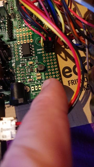
Bunch of holes on the edge of the midi/psu section


#1

So I found out after a couple of hours debugging that the +5 and GND in this section arent connected in rows as I had expected so only the hole by the label is connected. Given I had already soldered the headers and connected the external components I just connected them together across the back. Everything then worked as expected but is this ok ? Are any of those holes actually connected to anything else ?

I want to start using the others as a handy way to split a signal (eg, for I2C). am I likely to suddenly find one thats connected to something ?

A pic, follow the finger....

As you can see I have connected across on the 5v and GND but are the others safe to use ?


#2

gpio Pins are NOT 5v tolerant! 3.3v max. i hope you know that.


#3

Yep of course, although worth pointing out in case people misunderstood what I was doing.

I use the 5v to power my sharp distance sensors but wanted to feed the i2c from the axo into some rows of these and connect them up on the back, so I have multiple i2c connections direct off the axo board. I ended up running them to vero instead but it would be nice to know.

I have 5 x i2c devices that I am playing around with :slight_smile:


#4

perfect! sorry for "doubting" you :slight_smile:


#5

Not at all, readers may well have jumped to connecting their stuff to the 5v so its worth pointing out :slight_smile:
5v for power, 3.3 for sensors :+1:

Do you think its safe to assume the other non labelled holes aren't connected to anything ?
I am somewhat experiMental and expect to have a few 'faceplates' to plug direct to the board depending on whether I want pots, encoders and which i2c things I am playing with.


#6

Except for the labelled power points, these are blank solder points.


#7

Brilliant, thank you sevo, most useful.