Audio in (LIN+/-)


#1

Hi,
my board arrived today and it's awesome, thank you.

I'm getting strange voltages, if I'm trying to connect an audio signal to LIN- pin (non- & buffered input). There are no problems, if I connect the same signal source to the audio input jack.

What I'm doing wrong?

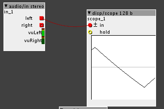
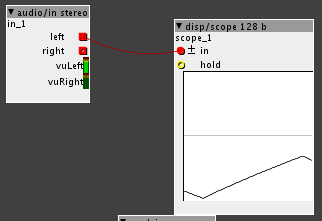
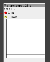
Some Screenshots from the axoloti scope:

Audio Jack Input:
Lin- Input:
Lin- pulled to GND (axoloti) via 10k resistor:

#2

Hi Paul,
LIN-, LIN+, RIN-, RIN+ are DC-coupled inputs of the audio codec, and biased (by the codec) at 1.65V.
You can find the 1.65V bias reference signal on the "CM" pad.
Your measurements are exactly as I would expect.
I don't really know what you intend to do.


#3

thank you for quick response.
I thought the LIN+/- pins are directly connected to the pins of the audio in jack. I want to the LIN+/- pins for audio in of my eurorack synth stuff. Therefor I buffered the input and use a simple resistor divider to attenuator the hot signal before LIn +/-.
Do you have any further information, how the input circuit should be?


#4

The 3 groups of 'R', 'S', and 'T' pads are connected to the jacks. R=ring (right), T=top (left), S=sleeve (ground).
They are organized in two rows, the row of pads close to the connectors are connected to the connectors, the row behind goes to the circuit. There are tiny traces on the backside of the circuit board between these rows.
So you can re-route the audio signals to external connectors, or re-purpose the jack inputs for, say, footswitch or foot controller pedal inputs.
The audio input is capacitively coupled. In eurorack it may be interesting to make DC-coupled inputs, in that case you will need LIN-/LIN+ etc, and a level shifter circuit.


#5

ok, thank you and nice circuit feature.
I found the old axoloti v3 eagle files on my hdd. Axoloti core uses the ADAU1961 ADC?

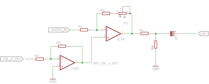
What do you thing about this input circuit:


#6

Hi Paul
You should add CM, not subtract CM, and after scaling. And why capacitive coupling the output?
The codec is adau361 (almost identical to adau1961).


#7

you're right. I looked at the examples of the adau1961 datasheet & I don't know if you put a capacitor between LINs and IC. the -cm was a fallacy.
Today my component order arrived and the first axoloti protoshield will be ready for testing tomorrow.


#8

I'm planning an application with DC-coupling, too.
As far as I can see (in axoloti-core-sch-v10.pdf), the ADC inputs RINP and LINP are not on a defined DC level, right? I'm thinking of removing C46 and instead connecting them to CM. Is there a special reason why you didn't so, @johannes? Just to be sure my idea is okay.


#9

RINP/LINP are biased internally to CM by the codec. C46 couples in the signal on the ground terminal of the audio input jack, canceling most ground loop noise. I don't think there is a need to remove C46, only if you're concerned about a tiny tiny DC offset caused by the leakage current of C46.